Download
1 / 51
510 likes | 521 Views
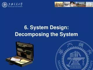
Chapter 6 System Design: Decomposing the System. Why is Design so Difficult?. Analysis: Focuses on the application domain Design: Focuses on the solution domain Design knowledge is a moving target The reasons for design decisions are changing very rapidly

E N D
Why is Design so Difficult? • Analysis: Focuses on the application domain • Design: Focuses on the solution domain • Design knowledge is a moving target • The reasons for design decisions are changing very rapidly • Halftime knowledge in software engineering: About 3-5 years • What I teach today will be out of date in 3 years • Cost of hardware rapidly sinking • “Design window”: • Time in which design decisions have to be made • Technique • Time-boxed prototyping
The Purpose of System Design Problem • Bridging the gap between desired and existing system in a manageable way • Use Divide and Conquer • We model the new system to be developed as a set of subsystems New System Existing System
1. Design Goals Defi nition T rade-of fs 8. Boundary Conditions Initialization T ermination System Design System Design Failure 2. System Decomposition Layers/Partitions Cohesion/Coupling 7. Software Control Monolithic Event-Driven Threads Conc. Processes 3. Concurrency 6. Global 4. Hardware/ Identification of Threads 5. Data Resource Handling Software Management Mapping Access control Security Persistent Objects Special purpose Files Buy or Build Trade-off Databases Allocation Data structure Connectivity
Overview System Design I (Today) 0. Overview of System Design 1. Design Goals 2. Subsystem Decomposition System Design II: Addressing Design Goals (next lecture) 3. Concurrency 4. Hardware/Software Mapping 5. Persistent Data Management 6. Global Resource Handling and Access Control 7. Software Control 8. Boundary Conditions
How to use the results from the Requirements Analysis for System Design • Nonfunctional requirements => • Activity 1: Design Goals Definition • Functional model => • Activity 2: System decomposition (Selection of subsystems based on functional requirements, cohesion, and coupling) • Object model => • Activity 4: Hardware/software mapping • Activity 5: Persistent data management • Dynamic model => • Activity 3: Concurrency • Activity 6: Global resource handling • Activity 7: Software control • Subsystem Decomposition • Activity 8: Boundary conditions
How do we get the Design Goals? Let’s look at a small example • Current Situation: • Computers must be used in the office • What we want: • A computer that can be used in mobile situations.
Identify Current Technology Constraints Direction where the user looks is irrelevant Single Output Device Fixed Network Connection Location of user does not matter Precise Input
Direction where the user looks is irrelevant Single Output Device Fixed Network Connection Location of user does not matter Precise Input Generalize Constraints using Technology Enablers Direction where the user looks is relevant Multiple Output Devices Dynamic Network Connection Location-based Vague Input
Establish New Design Goals • Mobile Network Connection • Multiple Output Devices • Location-Based • Multimodal Input (Users Gaze, Users Location, …) • Vague input
Sharpen the Design Goals • Location-based input • Input depends on user location • Input depends on the direction where the user looks (“egocentric systems”) • Multi-modal input • The input comes from more than one input device • Dynamic connection • Contracts are only valid for a limited time • Is there a possibility of further generalizations? • Example: location can be seen as a special case of context • User preference is part of the context • Interpretation of commands depends on context
List of Design Goals • Good documentation • Well-defined interfaces • User-friendliness • Reuse of components • Rapid development • Minimum # of errors • Readability • Ease of learning • Ease of remembering • Ease of use • Increased productivity • Low-cost • Flexibility • Reliability • Modifiability • Maintainability • Understandability • Adaptability • Reusability • Efficiency • Portability • Traceability of requirements • Fault tolerance • Backward-compatibility • Cost-effectiveness • Robustness • High-performance
Developer/ Maintainer Relationship Between Design Goals End User Functionality User-friendliness Ease of Use Ease of learning Fault tolerant Robustness Low cost Increased Productivity Backward-Compatibility Traceability of requirements Rapid development Flexibility Runtime Efficiency Reliability Portability Good Documentation Client (Customer, Sponsor) Minimum # of errors Modifiability, Readability Reusability, Adaptability Well-defined interfaces Nielson Usability Engineering MMK, HCI Rubin Task Analysis
Typical Design Trade-offs • Functionality vs. Usability • Cost vs. Robustness • Efficiency vs. Portability • Rapid development vs. Functionality • Cost vs. Reusability • Backward Compatibility vs. Readability
Nonfunctional Requirements may give a clue for the use of Design Patterns • Read the problem statement again • Use textual clues (similar to Abbot’s technique in Analysis) to identify design patterns • Text: “manufacturer independent”, “device independent”, “must support a family of products” • Abstract Factory Pattern • Text: “must interface with an existing object” • Adapter Pattern • Text: “must deal with the interface to several systems, some of them to be developed in the future”, “ an early prototype must be demonstrated” • Bridge Pattern
Textual Clues in Nonfunctional Requirements • Text: “complex structure”, “must have variable depth and width” • Composite Pattern • Text: “must interface to an set of existing objects” • Façade Pattern • Text: “must be location transparent” • Proxy Pattern • Text: “must be extensible”, “must be scalable” • Observer Pattern • Text: “must provide a policy independent from the mechanism” • Strategy Pattern
Section 2. System Decomposition • Subsystem (UML: Package) • Collection of classes, associations, operations, events and constraints that are interrelated • Seed for subsystems: UML Objects and Classes. • (Subsystem) Service: • Group of operations provided by the subsystem • Seed for services: Subsystem use cases • Service is specified by Subsystem interface: • Specifies interaction and information flow from/to subsystem boundaries, but not inside the subsystem. • Should be well-defined and small. • Often called API: Application programmer’s interface, but this term should used during implementation, not during System Design
Services and Subsystem Interfaces • Service: A set of related operations that share a common purpose • Notification subsystem service: • LookupChannel() • SubscribeToChannel() • SendNotice() • UnscubscribeFromChannel() • Services are defined in System Design • Subsystem Interface: Set of fully typed related operations. • Subsystem Interfaces are defined in Object Design • Also called application programmer interface (API)
Choosing Subsystems • Criteria for subsystem selection: Most of the interaction should be within subsystems, rather than across subsystem boundaries (High cohesion). • Does one subsystem always call the other for the service? • Which of the subsystems call each other for service? • Primary Question: • What kind of service is provided by the subsystems (subsystem interface)? • Secondary Question: • Can the subsystems be hierarchically ordered (layers)? • What kind of model is good for describing layers and partitions?
Modeling Authoring Workorder Repair Inspection Augmented Reality Workflow Subsystem Decomposition Example Is this the right decomposition or is this too much ravioli?
Definition: Subsystem Interface Object • A Subsystem Interface Object provides a service • This is the set of public methods provided by the subsystem • The Subsystem interface describes all the methods of the subsystem interface object • Use a Facade pattern for the subsystem interface object
System as a set of subsystems communicating via a software bus Authoring Modeling Workflow Augmented Reality Inspection Repair Workorder A Subsystem Interface Object publishes the service (= Set of public methods) provided by the subsystem
Repair Inspection Authoring Augmented Reality Workflow Modeling A 3-layered Architecture What is the relationship between Modeling and Authoring? Are other subsystems needed?
Tournament Component Management User Management Tournament Statistics User Directory User Interface Session Management Advertisement Another Example: ARENA Subsystemdecomposition
Tournament Component Management User Management Tournament Statistics User Directory User Interface Session Management Advertisement Services provided by ARENA Subsystems Manages advertisement banners and sponsorships. Administers user accounts Manages tournaments, applications, promotions. For adding games, styles, and expert rating formulas Stores user profiles (contact & subscriptions) Stores results of archived tournaments Maintains state during matches.
Coupling and Cohesion • Goal: Reduction of complexity while change occurs • Cohesion measures the dependence among classes • High cohesion: The classes in the subsystem perform similar tasks and are related to each other (via associations) • Low cohesion: Lots of miscellaneous and auxiliary classes, no associations • Coupling measures dependencies between subsystems • High coupling: Changes to one subsystem will have high impact on the other subsystem (change of model, massive recompilation, etc.) • Low coupling: A change in one subsystem does not affect any other subsystem • Subsystems should have as maximum cohesion and minimum coupling as possible: • How can we achieve high cohesion? • How can we achieve loose coupling?
Partitions and Layers Partitioning and layering are techniques to achieve low coupling. A large system is usually decomposed into subsystems using both, layers and partitions. • Partitions vertically divide a system into several independent (or weakly-coupled) subsystems that provide services on the same level of abstraction. • A layer is a subsystem that provides subsystem services to a higher layers (level of abstraction) • A layer can only depend on lower layers • A layer has no knowledge of higher layers
Layer 1 Layer 2 Layer 3 Subsystem Decomposition into Layers • Subsystem Decomposition Heuristics: • No more than 7+/-2 subsystems • More subsystems increase cohesion but also complexity (more services) • No more than 4+/-2 layers, use 3 layers (good)
Relationships between Subsystems • Layer relationship • Layer A “Calls” Layer B (runtime) • Layer A “Depends on” Layer B (“make” dependency, compile time) • Partition relationship • The subsystem have mutual but not deep knowledge about each other • Partition A “Calls” partition B and partition B “Calls” partition A
Virtual Machine • Dijkstra: T.H.E. operating system (1965) • A system should be developed by an ordered set of virtual machines, each built in terms of the ones below it. Problem VM1 C1 C1 C1 attr attr attr opr opr opr C1 C1 VM2 attr attr opr opr C1 VM3 C1 attr attr opr opr C1 VM4 attr opr Existing System
Virtual Machine • A virtual machine is an abstraction • It provides a set of attributes and operations. • A virtual machine is a subsystem • It is connected to higher and lower level virtual machines by "provides services for" associations. • Virtual machines can implement two types of software architecture • Open and closed architectures.
C1 C1 C1 C1 C1 C1 C1 C1 C1 VM1 attr attr attr attr attr attr attr attr attr op op op op op op op op op VM2 VM3 VM4 Closed Architecture (Opaque Layering) • Any layer can only invoke operations from the immediate layer below • Design goal: High maintainability, flexibility
C1 C1 C1 C1 C1 C1 C1 C1 C1 attr attr attr attr attr attr attr attr attr op op op op op op op op op Open Architecture (Transparent Layering) • Any layer can invoke operations from any layers below • Design goal: Runtime efficiency VM1 VM2 VM3 VM4
Properties of Layered Systems • Layered systems are hierarchical. They are desirable because hierarchy reduces complexity (by low coupling). • Closed architectures are more portable. • Open architectures are more efficient. • If a subsystem is a layer, it is often called a virtual machine. • Layered systems often have a chicken-and egg problem • Example: Debugger opening the symbol table when the file system needs to be debugged
Software Architectural Styles • Subsystem decomposition • Identification of subsystems, services, and their relationship to each other. • Specification of the system decomposition is critical. • Patterns for software architecture • Client/Server • Peer-To-Peer • Repository • Model/View/Controller • Pipes and Filters
Client/Server Architectural Style • One or many servers provides services to instances of subsystems, called clients. • Client calls on the server, which performs some service and returns the result • Client knows the interface of the server (its service) • Server does not need to know the interface of the client • Response in general immediately • Users interact only with the client
Client/Server Architectural Style • Often used in database systems: • Front-end: User application (client) • Back end: Database access and manipulation (server) • Functions performed by client: • Customized user interface • Front-end processing of data • Initiation of server remote procedure calls • Access to database server across the network • Functions performed by the database server: • Centralized data management • Data integrity and database consistency • Database security • Concurrent operations (multiple user access) • Centralized processing (for example archiving)
Design Goals for Client/Server Systems • Service Portability • Server can be installed on a variety of machines and operating systems and functions in a variety of networking environments • Transparency, Location-Transparency • The server might itself be distributed (why?), but should provide a single "logical" service to the user • Performance • Client should be customized for interactive display-intensive tasks • Server should provide CPU-intensive operations • Scalability • Server should have spare capacity to handle larger number of clients • Flexibility • The system should be usable for a variety of user interfaces and end devices (eg. WAP Handy, wearable computer, desktop) • Reliability • System should survive node or communication link problems
Problems with Client/Server Architectural Styles • Layered systems do not provide peer-to-peer communication • Peer-to-peer communication is often needed • Example: Database receives queries from application but also sends notifications to application when data have changed
Peer-to-Peer Architectural Style • Generalization of Client/Server Architecture • Clients can be servers and servers can be clients • More difficult because of possibility of deadlocks
Peer Client Server
Example of a Peer-to-Peer Architectural Style Layer Application • ISO’s OSI Reference Model • ISO = International Standard Organization • OSI = Open System Interconnection • Reference model defines 7 layers of network protocols and strict methods of communication between the layers. • Closed software architecture Presentation Session Level of abstraction Transport Network DataLink Physical
OSI model Packages and their Responsibility • The Physical layer represents the hardware interface to the net-work. It allows to send() and receivebits over a channel. • The Datalink layerallows to send and receive frames without error using the services from the Physical layer. • The Network layer is responsible for that the data are reliably transmitted and routed within a network. • The Transport layeris responsible for reliably transmitting from end to end. (This is the interface seen by Unix programmers when transmitting over TCP/IP sockets) • The Session layer is responsible for initializing a connection, including authentication. • The Presentation layer performs data transformation services, such as byte swapping and encryption • The Application layer is the system you are designing (unless you build a protocol stack). The application layer is often layered itself.
Another View at the ISO Model • A closed software architecture • Each layer is a UML package containing a set of objects
Application Object Presentation CORBA Session Transport Socket TCP/IP Network DataLink Physical Ethernet Wire Middleware Allows Focus On The Application Layer
initiator Controller 1 repository * Model 1 notifier subscriber View * Model/View/Controller • Subsystems are classified into 3 different types • Model subsystem: Responsible for application domain knowledge • View subsystem: Responsible for displaying application domain objects to the user • Controller subsystem: Responsible for sequence of interactions with the user and notifying views of changes in the model. • MVC is a special case of a repository architecture: • Model subsystem implements the central datastructure, the Controller subsystem explicitly dictate the control flow
Example of a File System Based on the MVC Architectural Style
2.User types new filename 3. Request name change in model :Controller 1. Views subscribe to event :Model 5. Updated views 4. Notify subscribers :InfoView :FolderView Sequence of Events (Collaborations)
Repository Subsystem createData() setData() getData() searchData() Repository Architectural Style (Blackboard Architecture, Hearsay II Speech Recognition System) • Subsystems access and modify data from a single data structure • Subsystems are loosely coupled (interact only through the repository) • Control flow is dictated by central repository (triggers) or by the subsystems (locks, synchronization primitives)
SemanticAnalyzer Repository SymbolTable ParseTree SourceLevelDebugger Examples of Repository Architectural Style Compiler • Hearsay II speech understanding system (“Blackboard architecture”) • Database Management Systems • Modern Compilers SyntacticAnalyzer Optimizer CodeGenerator LexicalAnalyzer SyntacticEditor