Download
1 / 40
400 likes | 496 Views
Senior Design Team 05910 RMSC Robotics Display. Mentor: Bill Scarbrough Mary Beth Belczak (ME) Matt Boecke (EE) John Byrne (ME) Jason Kelly (ID) Mike Rhault (ME) Amy Tatro (ME). Background. The Rochester Museum and Science Center has demonstrated an interest in changing their image.

E N D
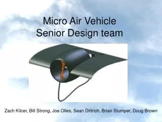
Senior Design Team 05910RMSC Robotics Display Mentor: Bill Scarbrough Mary Beth Belczak (ME) Matt Boecke (EE) John Byrne (ME) Jason Kelly (ID) Mike Rhault (ME) Amy Tatro (ME)
Background • The Rochester Museum and Science Center has demonstrated an interest in changing their image. • Recent developments have changed the museum from a place of observation to an interactive learning center. • The Rochester Museum and Science Center would like to increase the amount of hands-on exhibits at the center.
Robotics Display • The mission of this project is to create an interactive robotics display for the Rochester Museum and Science Center. • RMSC stressed that the project must meet eight basic requirements.
The display must be geared towards children ages 8-14. The exhibit must carry a high attractor factor. The display must allow the patron to interact with the exhibit. People who are not using the exhibit must be able to watch and be entertained. Prototyping will be a necessary step to eliminate the “Human Factor”. The experience at the exhibit does not have to be entirely educational. The exhibit should be easy to use without much instruction. A service manual should be provided for maintenance. RMSC Robotics Display Requirements
Introduction toConcept Development • This project has gone through many stages of concept development. • First, multiple project ideas were proposed to RMSC. • RMSC chose which idea to continue with. • Then, a final concept was proposed to RMSC. • RMSC gave feedback and concerns with the final proposal. • Lastly, the final concept was redesigned to overcome concerns. • The final design concept is a robotic arm that assembles a stop clock. • A second, user operated, robotic arm will be available for patrons to manipulate blocks while racing the clock.
Brainstorming • Over 30 project ideas were developed before the initial sponsor meeting. • After receiving specifications, some ideas were modified and others were eliminated. • Project ideas were consolidated and the top choices were ranked based on feasibility and needs assessment. • The highest ranking projects were proposed to RMSC.
Copy Cat Copy Movement Assembly Line Air Hockey Make-A-Maze Mobile Robots Question and Answer Race Proposed Projects
Copy Cat • Copy tasks performed by user. • User could stack blocks of different shapes and colors. • Robot will build the exact shape and color pattern.
Copy Movement • Robotic arm will mimic human motions. • Can be made into a game such as Simon says or bop it. • Patron will hit a series of buttons, bells, or levers and the robot will repeat their movements.
Make-A-Maze • Robots are trained to follow a path on the floor or wall. • Tiles will be able to be moved to create different courses for the robot. • Robots will be able to race to test the child’s maze making ability.
Mobile Robots • The display will consist of one or more differential drive vehicles. • The robots could be used in a tag or PACMAN style game.
Question and Answer Race • A robot will be allowed to travel a maze on one side of the exhibit. • The user will be on the other side trying to solve puzzles and answer questions. • Each correct answer advances their robot displayed on a screen. • The faster you answer, the faster you finish the race.
Assembly Line • A robotic arm is used to build a car from determined parts. • Patron selects buttons to determine body, tires and engine types. • A test cell will be in place to generate performance readouts.
Air Hockey • Full size air hockey table with patron on one side playing against a robot on the other. • Difficulty options will be made available. • Multiple tables could be used to entertain more patrons.
Accepted Introduction • After proposing the project concepts to RMSC, their top choice was the Air hockey exhibit, though a final decision had not been made. • In the interests of time, plans were developed for the Air Hockey exhibit. • The final decision, however, was for the Assembly Line exhibit.
Air Hockey Plans • Track sensors embedded in the playing surface. • Users can select the level of playing difficulty. • The puck speed is regulated by the robotic paddle. • A solenoid will speed up a slow puck. • A spring will dampen a fast puck. • A Cartesian robot is driven by a timing belt, powered by a stepper motor.
Air Hockey Plans • Two configurations are possible. • Air Hockey • Cartesian robotic player vs. patron • Pong • Cartesian robotic player vs. user controlled Cartesian robotic player
Assembly Line Final Proposal • After reviewing the proposals, RMSC accepted the assembly line proposal as the final project. • Patrons will use a touch screen to select body, wheel and engine type. • Robot assembles desired car on a dyno. • The dyno will then start and the user will be able to observe the characteristics of the vehicle they selected. • After the dyno test, the robot will disassemble the vehicle in reverse order.
Vehicles • The bodies and chassis will be vacuum formed. • Toy cars have been found and will serve as the mold. • The toy cars have tires that will be used to connect to the chassis. • Cars will be painted to appeal to both male and female patrons.
Final Concept Redesign • After reviewing the final proposal, RMSC expressed concern about the dyno not being genuine. • A new design was then determined to overcome this concern yet keep the exhibit interesting. • The new design used as many existing plans as possible.
Final Assembly Line Concept • A small robotic arm will assemble a stop clock. • A small user operated arm will be located next to this section of the exhibit. • The user can assemble blocks with the arm through the use of a remote control. • The user can race the newly assembled clock by building as many pillars of blocks as possible in the allotted time.
User Interface • User will use a touch screen to start robotic arm assembly. • User will use a remote control to operate second robotic arm.
Feasibility ofRobotic Arm Concepts • Each concept was assessed based on cost, scheduled time, human factor requirements, technical requirements, maintainability and benefits. • The concepts were ranked based on the other 5 and the scores were weighted and summed. • They were then compared to a purchased robotic arm and weighted accordingly.
Robotic Arm • A small robotic arm will be used to assemble all vehicles. • The arm’s maximum reach is 11in. • Due to repeat loading, we will replace 3 servos with a heavy duty version that can withstand a loading of 3lbs. • The arm will be fitted with an electromagnet to pick up the parts. (http://www.crustcrawler.com/products/arm5.php?id=menu0sub5)
Robot Track • To increase the robot’s area of reach, we will mount the robot to a straight track. • Track will be 4ft. long. • A rack and pinion will be used to move the robot along guide rails, driven by a stepper motor.
Guide Rail Stress and Deformation Analysis • The actual modulus of elasticity of the hardened aluminum guide rails is unknown. • Standard aluminum was analyzed. • The loading conditions are shown below. Assembly Weight Shaft Weight Rod ends constrained all degrees of freedom
Aluminum Model: Stress • Max Stress = 1044psi
Aluminum Model: Deformation • Max Deformation = 0.0218in
Stress and Deformation Conclusions • The yield stress aluminum is 50ksi. • The maximum stress of the guide rails is 1044psi, therefore the rails will not break under these loading conditions. • The maximum deformation found is 0.0218in. This deformation is negligible in the system.
Ff F ms x+ W F r v r w Drive Motor Torque and Speed Requirements • Torque Require to overcome maximum calculated force: • Maximum Force due to overcoming static friction. • Motor Speed Require for robot translational velocity:
Impact of Redesign:Air Hockey • The entire Air Hockey plans had to be scrapped in order to accomplish the Assembly Line project, including: • Electrical calculations • Electrical specifications • Vendor research of major components • Vendor research of electrical components
Impact of Redesign:Assembly Line The robotic arm and drive system will remain the same. • The electrical system has no changes as the robotics did not change. • Car parts are no longer necessary. Instead, gears and other clock parts will be machined. • Blocks will be machined for the user assembly area. • Remote controlled robot will be designed. At that time, robotic arm options will be assessed. • Most of the work accomplished before the redesign was maintained. • The redesign brings in much more design work.
Week 1: Project Selection Week 2: Project Selection Week 3: Brainstorming Week 4: Needs Assessment Week 5: Preliminary Concept Development Week 6: Preliminary Design for Air Hockey Robot Week 7: Final Project Selected, Brainstorming Week 8: Final Concept Development Week 9: Preliminary Design, Feasibility Week 10: Final Proposal Modification, Presentation and Report Preparation Project Schedule:Senior Design I
Project Schedule:Winter Quarter • Two additional team members will join the current team. • Their Senior Design I tasks will include: • Determining electrical components • Preliminary coding of the robotic arm • Developing a graphical user interface for the touch screen • Current team member tasks include: • Developing a complete design of clock parts • Designing a user activated robotic arm • Creating a drawing package of the display cabinet
Week 1: Fabrication Week 2: Fabrication, Operation and Testing Week 3: Fabrication, Operation and Testing Week 4: Operation and Testing Week 5: Prototype Phase I Week 6: Display Modification I Week 7: Prototype Phase II Week 8: Display Modification II, Display Aesthetics Week 9: Display Aesthetics and Report Preparation Week 10: Presentation and Report Preparation Project Schedule:Senior Design II