Download
1 / 15
150 likes | 418 Views
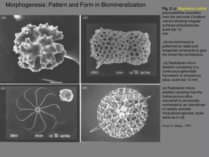
Morphogenesis: Pattern and Form in Biomineralization. Fig. 2 ( a ) Magnesium calcite polycrystalline concretion from the red coral Corallium rubrum showing irregular surfaces protuberances, scale bar 10 mm.

E N D
Morphogenesis: Pattern and Form in Biomineralization Fig. 2 (a) Magnesium calcite polycrystalline concretion from the red coral Corallium rubrum showing irregular surfaces protuberances, scale bar 10 mm. (b) the biomineral is patterned by radial and tangential constraints to give the wheel-like architecture. (d) Radiolarian micro-skeleton consisting of a continuous spheroidal framework of amorphous silica, scale bar 10 mm. (e) Radiolarian micro-skeleton showing how the hollow porous silica microshell is structurally connected to an internal set of radially-directed mineralized spicules; scale same as in (d). From S. Mann, 1997
Like any other type of phytoplankton, coccolithophores are one-celled marine plants that live in large numbers throughout the upper layers of the ocean. Unlike any other plant in the ocean, coccolithophores surround themselves with a microscopic plating made of limestone (calcite). These scales, known as coccoliths, are shaped like hubcaps and are only three one-thousandths of a millimeter in diameter. What coccoliths lack in size they make up in volume. At any one time a single coccolithophore is attached to or surrounded by at least 30 scales. Additional coccoliths are dumped into the water when the coccolithophores multiply asexually, die or simply make too many scales. In areas with trillions of coccolithophores, the waters will turn an opaque turquoise from the dense cloud of coccoliths. Scientists estimate that the organisms dump more than 1.5 million tons (1.4 billion kilograms) of calcite a year, making them the leading calcite producers in the ocean. In large numbers, coccolithophores dump tiny white calcite plates by the bucketful into the surrounding waters and completely change its hue.
Nacre (mother of pearl) in shells. Aragonite crystals formed in layers separated by protein sheets. A diatom: porous silica shell
Fig. 6.10 Cell Walls, intracellular organelles and cellular assemblages act as scaffolds for microtubules (MT) which in turn are used as directing agents for the patterns of vesicles (V) involved in biomineralization (B). From S. Mann 1997
Fig. VI.5 : Controls of biomineralization from supersaturated solutions 1) Gating via membrane pumps and redox processes 2) complexations w/ solubilizing agents 3) enzyme controlled concentrations 4) ionic strength (common ion effect) 5) pH 6) organic matrix- mediation insoluble organic compartments 7) matrix mediated nucleation, regulated direction of lattice growth 8) Epitaxy control: match dimension of crystal to pattern of template, so lattice spacing = amino acid residue spacing 9) Inhibitors
Magnetotactic bacterial cell containign chains of magnetite (Fe3O4) crystals, ~ 100nm in length.
Fig.6.4 shows different crystal morphologies of bacterial magnetite and their indexed faces. Crystal growth at different planes will produce various shapes.
General distribution of inorganic P with depth in the open ocean. Example at left was data taken from October 1988 to February 1989 at Station ALOHA in the central North Pacific, as part of the Hawaiian Ocean Time-series program (http://hahana.soest.hawaii.edu/hot/hot-dogs/interface.html).
General distribution of inorganic P with depth in the open ocean. Example at left was data taken from October 1988 to February 1989 at Station ALOHA in the central North Pacific, as part of the Hawaiian Ocean Time-series program (http://hahana.soest.hawaii.edu/hot/hot-dogs/interface.html). Why are these low near the surface?
From a report of: BIOMOLECULAR SELF-ASSEMBLING MATERIALS Scientific and Technological Frontiers, Panel on Biomolecular Materials Solid State Sciences Committee Board on Physics and Astronomy FIGURE 1 Illustration of the relationships among various aspects of biomolecular materials and their connections with the life sciences. Although still in its infancy, the application of biological principles to the development of new materials has already been demonstrated. A nucleus of broad-based research already exists, involving a variety of disciplines including chemistry, physics, biology, materials science, and engineering. The following specific examples of current research may help to give the reader an idea of the character of this exciting field: Polymer biosynthesis. Self-assembled monolayers and multilayers. Decorated membranes. Mesoscopic organized structures. Biomineralization. Biomolecular templates are being studied as nucleation devices for the synthesis of inorganic compounds with unusual structures and high degrees of perfection. Examples include the epitaxial growth of carbonates induced by molluscan shell protein and the intracellular synthesis of CdSe semiconductors.
SEM images of BaSO4 crystals grown at the waterchloroform interface with stearic acid (images A and B) and octadecylamine (images C and D) as the templating molecules in the organic phase. In the case of octadecylamine, the molecules at the interface would be positively charged at pH = 6.2 and therefore, the sulfate ions would be bound at the interface rather than Ba2+ ions as was the case with stearic acid molecules. We were interested in seeing whether the order of complexation of the ionic species prior to crystallization affected the morphology of the barite crystals grown at the liquidliquid interface. As mentioned earlier, chloroform is denser than water and therefore the orientation of both the stearic acid and octadecylamine molecules at the liquidliquid interface would be opposite to that in the case of waterhexane (below). A and B SEM images recorded from barite crystals grown at the interface between water and hexane with stearic acid in the organic phase at a supersaturation ratio of ca. 50. Debabrata R. Ray, Ashavani Kumar, Satyanarayana Reddy, S. R. Sainkar, N. R. Pavaskar and Murali Sastry* Materials Chemistry Division, National Chemical Laboratory, Pune, India CrystEngComm, 2001, 3, 213-216 Development of protocols to grow crystals of controllable structure, size, morphology and superstructures of pre-defined organizational order is an important goal in crystal engineering with tremendous implications in the ceramics industry. Lured by the exquisite control that biological organisms exert over mineral nucleation and growth by a process known as biomineralization, materials scientists are trying to understand biomineralization and, thereby, develop biomimetic approaches for the synthesis of advanced ceramic materials.
Fig. 5 (a) Cellular film of manganese(III/IV) oxide synthesized by reaction field templating in an oil droplet biliquid foam. The framework has cell sizes of 300 nm with continuous mineralized walls, 100 nm in thickness; note the additional higher-order morphological features (circular pits) with micrometre length scales, scale bar = 2 mm. (b) Hollow spherical shell of calcium carbonate (aragonite) formed by synthesizing a cellular mineralized film on polymer microspheres, scale bar = 200 nm. (c) BaSO4 ‘tentacles’ formed from coaligned crystalline nanofilaments produced by synthesis in supersaturated microemulsions at room temperature, scale bar = 500 nm. (d) Individual BaSO4 nanofilaments and a coiled morphological form synthesized as in (c) scale bar = 200 nm. (e) Micro-skeletal calcium phosphate synthesized in frozen-oil bicontinuous microemulsions, scale bar = 500 nm. ( f ) Silica microstructure produced by alkoxide condensation reactions in bicontinuous microemulsions, scale bar = 1 mm
Fig. 4 (a) Spiral outgrowth of calcium carbonate formed by growing crystals in the presence of 10 mg dm23 of a linear poly a,b-aspartate of Mr 7100, scale bar 100 mm. (b) Hierarchical morphology of BaSO4 crystals formed in a 0.5 mM aqueous solution of polyacrylate of Mr 5100; scale bar 10 mm. The cone-shaped units develop on the rim of pre-existing cones, and each cone consists of myriad BaSO4 nanofilaments (inset, scale bar 1 mm). (c) Self-assembled helical ribbon of a silica-phospholipid biphase, scale bar 200 mm. (d) Thin section showing a continuous silica framework produced by bacterial templating. The porous channels (white circles) are viewed end-on and are approximately 500 nm in width, scale bar 500 nm
A Hypothetical Model for Dental Enamel Biomineralization 1. Amelogenins are synthesized and secreted by ameloblast cells. 2. Amelogenin molecules assemble into nano-sphere structures approximately 20 nm in diameter with an anionic (negatively charged) surface. 3. The nanospheres interact electrostatically with the elongating surfaces of the enamel crystalites, acting as 20nm spacers that prevent crystal-crystal fusions. Enzymes (Proteinase-1) eventually digest away the charged surface of the nanospheres, producing hydrophobic nanospheres that further assemble and stabilize the growing crystalites. 4. Finally, other enzymes (Proteinase-2) degrade the hydrophobic nanospheres, generating amelogenin fragments and other unidentified products (?), which are resorbed by the ameloblasts. 5. As the amelogenin nanosphere protection is removed, crystallites thicken and eventually may fuse into mature enamel.