Download
1 / 32
340 likes | 615 Views
Grid Connect Inverters NUER 19. Basic Principles. What is an Inverter?. A Solid State Device which main job is to convert a Direct Current Supply to an Alternating Current Supply Inverter Symbol. An Inverter converts this Direct Current Input Wave Shape.

E N D
Grid Connect InvertersNUER 19 Basic Principles
What is an Inverter? • A Solid State Device which main job is to convert a Direct Current Supply to an Alternating Current Supply • Inverter Symbol
An Inverter converts this Direct Current Input Wave Shape To this Alternating Current Output wave shape
By using many very high speed switching devices an inverter is able to convert a series of precise D.C. Pulses into a synthesised A.C. Wave shape
Inverter Principle of Operation • Basically a 4 way switching bridge is used to re-route the direct current to alternate it at a set frequency through the load.
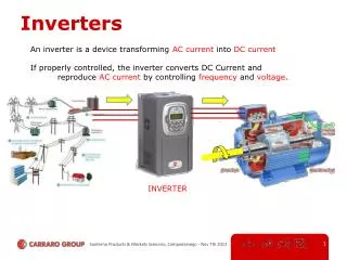
The Roles of a Grid Connect Inverter To convert D.C. from the generating source Photovoltaic Array or Wind Turbine etc into an A.C. Wave that is then transformed and synchronised with the electricity grid May Provide galvanic (voltage) isolation between the D.C. side and A.C. sides To extract the maximum amount of energy from the generating source Called Maximum Power Point Tracking (MPPT) To log and display electrical data from the array such as Energy, Power Voltage Current, $ Income & CO2 offset System monitoring and protection over: current, temperature & voltage Earth fault & arc fault detection etc
Basic Portable Inverter Circuit with MOSFET’s and Centre Tap Transformer
Internal Inverter Components • Switching Devices Transistors MOSFET’s/IGBT’s • Double Wound Transformer • Diodes • Thermistor’s • Surge diverter MOV’s • Fuses • Filtering Inductors and Capacitors
PN Junction Diodes Cathode Anode Diodes are semi conductor devices consisting of a PN Junction the P is the anode and the N is the cathode. When a positive charge is placed on the anode & negative is place on the cathode the diode conducts and is said to be forward biased. If a negative is placed on the anode and positive on cathode the diode is said to be reverse biases and the diode will not conduct
Bridge Rectifier Converts A.C. Supply in to Basic D.C. Supply Symbol Input wave shape Bridge Rectifier Output wave shape Bridge Rectifier
MOSFET TransistorMetal Oxide Semi Conductor Field Effect Transistor • Two N type semi Conductors within a P type base • When the gate is pulsed positive a electron bridge is created and current can flow through the source and drain. MOSFET symbol
IGBTInsulated Gate Bipolar Transistor The insulated-gate bipolar transistor or IGBT is a three-terminal power semiconductor device, noted for high efficiency and fast switching. It switches electric power in many modern appliances: electric cars, variable speed refrigerators, air-conditioners, and even stereo systems with digital amplifiers. Since it is designed to rapidly turn on and off, amplifiers that use it often synthesize complex waveforms with pulse width modulation and low-pass filters.
Double Wound Transformer Used for stepping the input voltage up or down providing galvanic isolation and helps with smoothing out the sin wave
Types of Wave Shapes of Inverters • Square Wave • No voltage regulation, cheap and nasty, limit to type of appliances that can be run off it • Modified Square Wave voltage • Still a square wave except the voltage is Regulated by Pulse Width Modulation (PWM) • True Sin wave (PWM with filters) less than 5% total Harmonic Distortion
Pulse Width Modulation to create a True Sine Wave Pulse width modulation is a technique used to create sinusoidal wave from a series of coded D.C. pulses called a pulse train. For the pulse train to become Smooth like a true sin wave a capacitive inductive filter must be used.
Classifying Grid Connect Inverters • Method of Commutation • Line Commutated • Self Commutated • Transformer/ Transformerless • How P.V. Array and Inverter Interface • Modular (at the modules) • String Inverter • Multi String • Mini Central • Central
Line Commutated Inverters Using a thyristor Bridge arrangement the thyristor’s are switched (commutated) By alternated pulses from the grid. These are known as grid controlled inverters and when the grid falls these inverter will automatically stop
Self Commutated Inverters Same Principle as Stand Alone Inverters Using Pulse width modulation switching devices are MOSFET’s or IGBT Must be used with a Grid Protection Device To ensure safety of the line workers when the grid goes down.
Transformer Classifications Based on Transformers • Low Frequency Transformer (Safe, reliable, lowest efficiency very heavy) Galvanic Isolation
HF Inverters • High Frequency Transformer (Galvanic Isolation, no iron Core, Tx very light and more efficient than Low Frequency Tx more complicated electronics)
Transformerless Grid Connect Inverters • No Tranformer (transformerless) (No galvanic isolation cheap to build most efficient has some serious safety concerns)
Multi String Inverter Dual MPPT so that two completely separate arrays can be inputed into the inverter with no efficiency consequences . Can have East West Facing Arrays
Central Inverters • Used for Large Solar Farms/Parks where the solar access is uniform across the park
List the Advantages and Disadvantages of Central Inverter over Multiple string Inverters