Download
1 / 45
450 likes | 628 Views
Status of Virgo. M.-A. Bizouard LAL-Orsay On behalf of the Virgo Collaboration Moriond Gravitation – 23/03/03. Contents. Highlights in 2001 & 2002: February 2001- July 2002: Commissioning of the Central part of the interferometer (CITF)

E N D
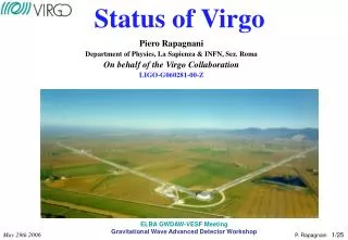
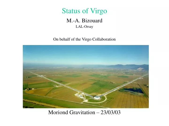
Status of Virgo M.-A. Bizouard LAL-Orsay On behalf of the Virgo Collaboration Moriond Gravitation – 23/03/03
Contents • Highlights in 2001 & 2002: • February 2001- July 2002: • Commissioning of the Central part of the interferometer (CITF) • CITF characterization: what we have learnt from the machine • Improvements and upgrades • Winter 2002: Virgo arms construction and assembly is over! • Plan: • Summary/main steps of the CITF commissioning • Performance of the CITF detector • Data analysis preparation in Virgo • Now: Upgrade to Virgo
Virgo optical scheme L=3km Finesse=50 Input Mode Cleaner Length = 144 m Recycling L=3km Finesse=50 Laser Nd:YAG P=1kW P=20 W Output Mode Cleaner Length = 4 cm
Input Mode Cleaner Length = 144 m West mirror 5.6 m Recycling Laser Nd:YAG 6 m 6.4 m P=10 W North mirror Output Mode Cleaner Length = 4 cm CITF optical scheme
Input Mode Cleaner Length = 144 m West mirror Recycling Laser Nd:YAG P=2mW P=20 W North mirror P=100mW Output Mode Cleaner Length = 4 cm Auxiliary laser CITF commissioning optical scheme
CITF versus Virgo • The CITF has been a full test of the Virgo design: • Same suspensions • Same digital controls • Same injection system • Same detection system • Same software • Main differences: • Only 2 lengths to be controlled (2 FP cavities less) • Smaller mirrors (less stringent quality requirements) • Goals: test the technical choices • super-attenuator, fully digital control, ….
West mirror Recycling North mirror Auxiliary laser West mirror Recycling North mirror Auxiliary laser CITF commissioning main steps • Simple Michelson: Feb 2001 (9 months) • Only 1 length to control • Test and validation of the suspensions control Eng.Runs 0 & 1 • Recycled Michelson: Nov 2001 (7 months) • Control 2 coupled lengths • Laser frequency stabilization Eng. Run 2 • Auto alignment of the dark fringe lengthEng. Run 3 • Recycled Michelson with injection system: Jun 2002 • More power available • Mode Cleaner (beam stabilization) Eng. Run 4
Engineering Runs • 5 ERduring the CITF commissioning • 3 days duration • The 2 first in Michelson configuration • The 3 others Recycled configuration • Goals: • To take data in stable ITF conditions detector characterization by offline data analysis • To fix milestones in the commissioning improvements • Duty cycles:ER0: 98% ER1:85% ER2: 98% ER3: 96%ER4: 73% • Long period of lock : 51 hours during ER0 • No trouble due to “normal human activities” during day time • Main sources of lock losses: human errors, control failures and alignment absence: understood! • ER4 low duty cycle due to problem of control of the light injection system (backscattered light from recycling mirror)
Long period (~hour) of unlocked interferometer due to back scattered light from recycling mirror into the injection system Huge variation of power 14 hours Interferometer is locked E4 duty cycle Power stored in the recycling cavity
Detector characterization • Lots of improvements during 2 years detector characterization • 10 Working groups: • Suspension performance • Locking performance • Alignment performance • Laser performance • Detection performance • Environmental noise • Lines identification • Noise glitches search • Noise stationarity and Gaussianity • Noise calibration • Lots of details during the talks of L. Barsotti, E. Cuoco, I. Fiori, P. LaPenna and F. Ricci on thursday
Alignment noise Electronic photodiode noise 09/01 / E0 12/01 / E1 04/02 / E2 05/02 / E3 Frequency laser noise 4 orders of magnitude to gain 07/02 / E4 Payload resonances CITF sensitivity improvements Expected Virgo
10-14 @ 10 Hz Virgo suspensions Super-attenuator = 7 stages inverted pendulum • Passive role: expected seismic attenuation : 1014 @ 10Hz • Active role: suspension control from: • the top stage, • the marionette, • the recoil mass • Requirements: control of the mirror position: longitudinal movement: 10-12 m
Interferometer control • Local controls: individual suspension control with respect to the ground: • Inertial Damping (damp the low frequency Inverted Pendulum resonances) • Mirror Local Controls (reduce the angular residual mirror motion to few μrad) • Global control: control collectively the longitudinal motion of all the mirrorsas well as their linear alignment switch from local to global control
10-14 @ 10 Hz Inertial damping performance Simulation • Role of the inertial damping:Freeze the Inverted Pendulum below 4 Hz • Method:Active top stage control using local position measurement rms residual mvt: 1 μm & 1 μrad • Improvement:Reduction of the 30 mHz bump introduced by the control loop (low phase margin) Z(μm) Z(μm) Position in horizontal plane (xz) of the Recycling suspension Inverted Pendulum before after X(μm) X(μm)
Robustness test of the Inertial Damping to Earthquake 5 May 2002 magnitude 3.3Epicenter: Orciano Pisano (~20 km from Virgo)
Robustness test of the Inertial Damping to Earthquake IP horizontal d.o.f. displacement just before the earthquake IP horizontal d.o.f. displacement during the earthquake 60 mm Beam Splitter North Input Beam Splitter North Input Recycling West Input Recycling West Input
Seismic wall begins to be visible below 2 Hz Local control noise reduction below 10 Hz Recycled interferometer sensitivity was limited by the angular control noise between 1 and 10 Hz: A new design of the control filter reduced the noise re-injection by up to 2 orders of magnitude @ 2 Hz !
Seismic attenuation direct measurement • Goals:measure the attenuation factor of the ground seismic noise compare the seismic noise attenuation at the level of the mirror to the thermal pendulum noise • Pisa region seismic noise: ~ for f < 20 Hz (horizontal & vertical) • Thermal pendulum noise: ~ The attenuation factor must be smaller than Measure: noise (lines) injected on the top stage (vertical and horizontal) if not detected at the mirror level upper limits Horizontal displacement Vertical displacement
Detector characterization • Suspension performance • Locking performance • Alignment performance • Laser performance • Detection performance • Environmental noise • Lines identification • Glitches search • Noise stationarity and Gaussianity and linearity • Noise calibration
Laser performance • Commissioning done apart due to problems and delays • Mode Cleaner length noise still too high for Virgo above 30 Hz: too large frequency noise (the laser frequency is locked on the MC length) the E4 sensitivity was limited by laser frequency noise below 300 Hz Coherence between MC length noise and dark fringe signal Cause: resonances of the Mode Cleaner bench ??? Replacement of the Mode Cleaner bench by a suspended Mode Cleaner mirror is now on progress … hope to reduce resonances. E4 data frequency
Detector characterization • Suspension performance • Locking performance • Alignment performance • Laser performance • Detection performance • Environmental noise • Lines identification • Glitches search • Noise stationarity and Gaussianity and linearity • Noise calibration
Detection system performance • A suspended detection bench (optics + Mode Cleaner) • An external bench (photodiodes) • CITF commissioning: the bench was on the ground • Output Mode Cleaner: rigid triangular cavity locked via temperature slow lock acquisition but very robust! Output Mode Cleaner main features: • Increase the contrast by a factor 10 • But the CITF auto alignment was crucial to keep the Mode Cleaner locked ! Lots of optical changes and software improvements foreseen for Virgo Dark fringe beam before the OMC Dark fringe beam after the OMC
Detector characterization • Suspension performance • Locking performance • Alignment performance • Laser performance • Detection performance • Environmental noise • Lines identification • Glitches search • Noise stationarity and Gaussianity and linearity • Noise calibration
Glitches search • Goal: look for “technical noise” in the different channels • Very simple algorithms sensitive to fast fluctuations • Problems detected: • Electronic boards failure (ADC boards) very few sample ADC count increase, fuzzy value and strange offset observed • Abrupt & short loss of power of the auxiliary laser • Detection picomotors used for realignment: electrical pick up by the photodiodes • Hardware (spikes incoil currents) • Problems to be solved for Virgo
Detector characterization • Suspension performance • Locking performance • Alignment performance • Laser performance • Detection performance • Environmental noise • Lines identification • Glitches search • Noise stationarity and Gaussianity and linearity • Noise calibration
Non stationary noise (E4 data) Time frequency diagrams over the 3 days Auto alignment on Ref. Cavity ON Mode cleaner control loop gain reduction
Non stationary noise New lines apparition Lines drift Auto alignment (E3 & E4) reduced a lot the non stationarities …. But there are still Some correlated with beam source noise
Detector characterization • Suspension performance • Locking performance • Alignment performance • Laser performance • Detection performance • Environmental noise • Lines identification • Glitches search • Noise stationarity and Gaussianity and linearity • Noise calibration
Noise calibration • Goal:determine the constant to apply to convert photodiode signal (V) into displacement units. • Effect of the control feedback is taken into account measuring the close loop transfer function • The absolute conversion (V / m) is determined by the open loop transfer function • CITF calibration results: close loop transfer function measurement : • A dependency wrt to power stored in the recycling cavity has been observed. • A dependency wrt to the locking correction signal has also been observed (not foreseen … maybe due to non linearities in the actuators (coils)) • Upgrade to Virgo: Optical calibration • Act on mirrors (North and West Input) with the radiation pressure of a laser • Will be tested for Virgo in the following months
Thermal noise in the E4 sensitivity • Above 1 kHz, some of the peaks have been identified as West Input payload internal resonances • Peak amplitude are compatible with the expected thermal noise • Thermal noise model: • Peaks frequency and QF estimated from the payload transfer function • The effective mass has been fitted
Summary of the CITF commissioning • Validate most of the Virgo technical choices(super-attenuator, digital controls, output Mode Cleaner…) • Reveal problems in the beam source system • Lots of improvements in the control feedback • Gain in the sensitivity: 105 @ 1kHz 103 @ 10 Hz in 18 months • Sensitivity main limitation: • Below 10 Hz: alignment solution: Auto Alignment • Above 10 Hz: noise of the Mode Cleaner length solution: MC bench replacement by a MC payload 6 papers in preparation about the CITF performances
Data analysis preparation in Virgo • Organization in working groups: • Binaries group (NS/NS, BH/BH, NS/BH) • Burst group (Supernova,merger phase of BH/NS binaries) • Pulsar group • Stochastic background group • Noise group (detector characterization) • Active members: < 10 in each group ….
Burst group highlights Signal:short duration (<10 ms) badly modeled waveforms robust but sub-optimal filters • Lots (7+) of robust sub-optimal filters have been developed • Definition of a benchmark to compare the filters (efficiency, timing, robustness) • Algorithm to optimally tile with templates a 2D parameter space: • used in the case of damped sine signals search (QNM of excited BH) • has shown that the fraction of lost events is reduced to 1-MM0.74 instead of 1-MM3 • Coincident and coherent burst search with other detectors • 4 papers published in PRD in 2002
Binary coalescence highlights Signal: long chirp before the coalescence waveform modeled in PN formalism use of Wiener filtering techniques • Gather codes for templates production: • spinless • PN up to 2.5 • Taylor, Pade and EOB • Grid templategeneration algorithms: several developed, to be compared • Development of hardware parallel architecture for match filtering • Organization of a Mock Data Challenge (4/8 April 2003): • Generation of a large grid of templates • Produce templates • Test of the hardware nodes using simulated data (ER4 power spectrum) • Measure the efficiency (ROC) Points out the work to be done in order to be ready in 2004!
Pulsar highlights Signal: permanent, sinusoidal and weak amplitude follow pulsar frequency on large timescales (~ year) (compensation of Doppler frequency shifts) • Scan of the whole sky large computing power (~ 1012Tflops) hierarchical methods (~ Tflops) • Focus on known pulsars Work done: • Hierarchical search for low spindown single NS sources • Detection of pulsar in binary system with high spindown • Test of Grid technology to solve the problem of huge CPU request
Virgo upgrade to 3 km Vacuum: OK • 3 km arms tubes installed, baked at 150° C • 3 leaking welds (out of 440): repaired • All towers and valves installed • Very high quality vacuum (under spec.) • Now:North arm under vacuum P< 10-9 mbar • P(H2) = 2.10-10 mbar • P(hydrocarbon) ~ 10-14 mbar
Virgo upgrades Beam source: complete end of may 2003 • 20 W laser installed and: OK • New laser bench with pre Mode-Cleaner: OK • MC bench replaced by a mirror: end of may 2003 Detection system: complete end of may 2003 • Upgrade for larger and more powerful beam: end of may 2003
Suspension upgrades Suspension upgrade: complete in may 2003 • Terminal towers installed in 2002 • Now: • Mechanical tuning of end arm suspensions • Local controls improvements (longitudinal control is new!) • Thermal stabilization (ΔT < 1°C) to reduce long term vertical displacements : 6mm/K Heating belts around the tower • Installation of the monitoring and steering 16 and 32 mHz resonances from the filter 7
Virgo mirrors installation • Virgo mirrors are produced at SMA-Lyon laboratory • Very low losses: • scattering < 5 ppm • absorption < 1 ppm, • transmission : 10 < T < 50 • Uniformity on large dimension: < 10-3 on 40cm • All Virgo mirrors have been delivered fulfilling the Virgo requirements • Installation: • Recycling, beam splitter, north input : already installed • North end, West input and West end: complete end of may 2003
Commissioning of Virgo/planning • Start-up : end of May 2003 • Strategy: • first lock and study the North arm FP cavity • Virgo locking • Commissioning plan: under discussion • Duration: ~2 years • Several Engineering Runs in 2003/2004 • First Science Run: 2004? • Pre-commissioning already started beginning of 2003: • Alignment of the North arm using an auxiliary laser: 13 march 2003
Let there be light …. 10 mW He-Ne auto collimated laser at the end of the North arm
f<70 mHz no feedback to top stage 3.5 mN with feedback to top stage f>70 mHz Active control to the top stage Motivation for active control: one has to compensate • the seismic movements at low frequency, • the tidal movements (δl =1mm over 3 km), • The long term drifts in the suspension chain Dynamic control range: • Mirror/marionette control dynamic: few tens of microns • Top stage control dynamic: few mm Split the force correction signal between the 2 control stages Reduce the force applied to the mirror by 10 (reduction of the noise!) Reduce by factor 3 the angular movement induced by coils control Reduce non linear effects due to Foucault current in coils low frequency high dynamic