Download
1 / 36
360 likes | 471 Views
5 th CLIC-ACE Structure production in laboratories and industries. G. Riddone, 02/02/2010 (contribution from KEK/SLAC colleagues). Content. Introduction to RF structures and components Fabrication baseline procedure for accelerating structures

E N D
5th CLIC-ACE Structure production in laboratories and industries G. Riddone, 02/02/2010 (contribution from KEK/SLAC colleagues)
Content Introduction to RF structures and components Fabrication baseline procedure for accelerating structures Application to CERN accelerating structure fabrication Fabrication of PETS RF structure production capability RF structure master schedule Present structures (CERN, KEK, SLAC, Elettra, PSI) Towards CLIC structures (CDR, TDR)
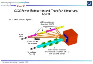
Introduction PETS (12 GHz, TBTS) TD24#2 at CERN (12 GHz) TD18#3 at SLAC TD18#2 at KEK Hybrid High-power dry load PETS (11.4 GHz, test at SLAC) Variable high power splitter
Fabrication of accelerating structures T18 structures tested at SLAC/KEK showed excellent test results consequent validation of design, machining and assembly procedure NLC/JLC fabrication technology: validated to 100 MV/m (baseline for future CERN X-band accelerating structures)
Baseline procedure Diamond machining (sealed structures) Cleaning with light etch J. Wuang H2 diffusion bonding/brazing at ~ 1000 ˚C Vacuum baking 650 ˚C > 10 days J. Wuang
Application to CERN accelerating structures • CERN previous assembly procedure was based on vacuum brazing at 800 ˚C several changes were needed for implementing the baseline procedure • Following the post-mortem analysis of the two CERN accelerating structures T18 and T24, contamination (C, Ca) resulted to be the main problem cleanliness had to be seriously improved
Baseline manufacturing flow High precision diamond machining QC Machining of couplers Brazing of couplers (H2, 1045 °C, AuCu) Cleaning (light etch) Diffusion bonding of disk stack (H2, 1020 °C) RF check and tuning Brazing of coupler bodies, cooling circuits, tuning studs (AuCu, 1020 °C) Packaging and shipping Baking (vacuum, 650 °C, >10 d) New for CERN
Inspections Microscopic inspection of disks before and after cleaning (on witness pieces) Microscopic inspections before and after each relevant fabrication step T18 KEK/SLAC design Video inspections, SEM and microscopic inspections
Machining at VDL All dimensional checks are conform Damped disk at 12 GHz Shape tolerance ±2.5 mm New CMM (Coordinate Measuring Machine) under procurement at CERN
Cleaning SLAC cleaning procedure as a baseline For degreasing Trichloroethane at SLAC replaced by Perchloroethylene CERN procedure: (Firm AVANTEC Performance Chemicals): - TOPKLEAN MC 20A - PROMOSOLV 71IPA J. Wuang Etching Tool for holding the disks
Diffusion bonding couplers 1045 °C, 2 h Disks T18KS Couplers + disks TD24 1020 °C, 1.5 h TD24 Bonding at CERN: few mbar H2 partial pressure (difference with SLAC): we are actively looking for a furnace at 1 bar H2 in Europe.
Accelerating structure TD24 after diffusion bonding under H2 Large grain size!
Assembly At SLAC Assembly made on V-blocks Verification of the assembly (before and after bonding) with a new measurement column: straightness and tilt Straightness measurement ±2 mm
RF check and tuning New test set-up is under procurement for RF measurements T24#1 Bead pulling at 11.421GHz (old test-set-up) Before shipping RF check and tuning were done and results were good
Vacuum baking CERN furnace several mechanical adaptations were needed 10-9 mbar 1st baking: TD24 for CLEX, two-beam test stand J. Wuang
Clean room • After the failure of CERN ac. structures, it became clear that a clean room was indispensable • - Audits for relevant steps organized Clean room layout Clean pieces CLEAN ROOM with AIR CONDITIONING VESTIBULE RF measurement Boxes under N2 Sealed bag under N2
Fabrication of PETS at 11.4 GHz with damping material Damping material Bar length ~ 300 mm Shape tolerance within specification: ± 7.5 mm Minitank with bars inside • PETS for feasibility demonstration • under assembly • to be tested at SLAC Coupler
Fabrication flow for PETS (11,4 GHz) Procedure as close as possible to the baseline, but some difference due to design and infrastructures RF check Assembly of the 8 bars QC Vacuum test EB welding of the bars Cleaning (NGL+solvent) Final bake-out (150 C, 2h) RF check PETS bars FINAL ASSEMBLY EB welding of the bars Packaging (N2) Assembly of couplers-bars and mini-tank Baking (vacuum, 200 C, 2 h) Shipping to SLAC EB welding of tank
Fabrication of TBL PETS Prototype made by CIEMAT using conventional UHV best practice for cleaning and handling Coupler is brazed, no heat treatment for PETS itself The CERN production will be assembled in a clean room, The coupler will be vacuum brazed at CERN Status: parts fabrication, assembly should start in April S. Doebert
Production capability 3 laboratories: - ac. structures SLAC/KEK and CERN - PETS CERN 5 qualified vendors for ac. structures: 2 (CERN), 2 (KEK), 1 (SLAC) • 3 qualified vendors for PETS For each structure, at least two units per lab. are manufactured (almost in parallel) For KEK/SLAC made structure, the assembly/baking is made at SLAC - e.g. baking of two structures in parallel At present, potential capability up to 20. structures per year
Present structures: CERN, KEK, SLAC (base and fundamental program) TD24 CD10
Present structures: CERN(base program) 1 ac. structure (CLEX, TBTS) TBTS: two beam test stand SATS: stand-alone test stand 2 ac. structures with wakefield monitors (CLEX, TBTS)
Master schedule Monthly revised during the KEK-SLAC-CERN collaboration WebEX meetings Last revision:” 28.01.2010
Comparison to Jan 2009 schedule • For production overall delay of about 4 months, although not on critical path • Priorities change as a function of test results • CERN structures: break of few weeks before decision to adopt baseline procedure • Several steps of baseline procedure were new for CERN: process qualification needed before application to a real structure • Baseline procedure takes longer than the previous based on vacuum brazing at 800 °C • Qualification of new vendors: several trials before achieving disks within specification
Other structures • Important involvement of other laboratories to exchange experience and to increase the market • 900-mm long structures for PSI (X-FEL) and Elettra (Sincrotone Trieste) with wakefield monitors • 72 cells Wakefield monitor design Structure assembly
Towards CLIC structures AS Wakefield monitor • CDR • Accelerating structure with all features: damping material, wakefield monitor and technical systems; under eng. design (first structure at the end of 2010). Assembly test with a prototype structure are scheduled in the coming weeks. • PETS with on-off system: under design. On-off system to be tested in Q3, 2010 • Cost estimate in needed by 2010: launched dedicated studies with three companies/institutes Damping material PETS Coupler On-off system
Towards CLIC structures • From CDR to TDR • Main linac prototype modules (3 by end of 2012) will be built to validate the technical systems in an integrated approach. T4 T1 T0 • These modules will contain accelerating structures and PETS with all required features • Industrialization and mass production development in collaboration with companies
Conclusions • NLC/JLC fabrication technology validated for CLIC accelerating structures to 100 MV/m • CERN is implementing NLC/JLC procedures (still in learning process) • Cleaning (etching) • Diffusion bonding at ~1040 °C (H2) • Vacuum baking • Production capability up to 20 structures per year higher than available testing slots • Involvement of other laboratories to exchange experience and expertise • CLIC structures with all features under design: first unit ready by end of this year • Main linac prototype modules for CLEX will include CLIC several structures • Industrialization, mass production and cost study launched for few structure configurations
T18 and before T24 Assembly of accelerating structures
QUADRANTS - HDS thick qualification part according to CLIAAS300062 - KERN (DE) S. Atieh Achieved shape accuracy ± 2.1 µm Roughness Ra = 86 nm – 30 nm according to ISO 97 Achieved shape accuracy ± 1.3 µm
QUADRANTS - HDS thick qualification part according to CLIAAS300062 – DMP (SP) S. Atieh Origins translation: X 16 µm and Z -8 µm Shape accuracy is respected ± 2.5 µm
T18 CERN - Inspection on iris 12 Contamination between brazing and testing C Ca C 35 35