Download
1 / 15
150 likes | 315 Views
EFAC Review. Conventional Facilities Update Marty Fallier Director for Conventional Facilities May 10, 2007. Outline. Conventional Facilities Deliverables for XFD Overview of Conventional Facilities Scope Experimental Floor Beamline Support Space – LOB ’ s Utility Services for XFD

E N D
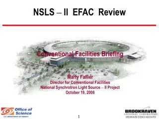
EFAC Review Conventional Facilities Update Marty Fallier Director for Conventional Facilities May 10, 2007
Outline • Conventional Facilities Deliverables for XFD • Overview of Conventional Facilities Scope • Experimental Floor • Beamline Support Space – LOB’s • Utility Services for XFD • Stability Strategy • Schedule Dependency
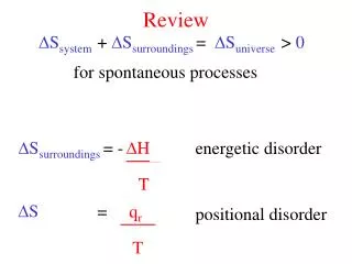
CF Deliverables for XFD • Provide a facility that promotes collaborative leading edge research in a pleasant working environment • Structurally stable facility with low vibration (<25nm Rms) • Tunnel design that provides required shielding and accessibility • Experimental floor temperature stability of +/- 0.5 deg C • Utility capacity & shielding for up to 3.6 GeV operation • Utility services for anticipated full suite of beamlines (60m) • Facility layout that enables future long beamlines • Facility design enabling future expansion to support full beamline build-out
NSLS II Facility Overview NSLS JPSI LOB (1 of 5) NSLS II CFN BLOC Service Bldgs (1 of 5) Access Tunnel
NSLS II Facility Overview cont’d • NSLS II Floor Plan • BLOC – Booster/LINAC/ Operations Center • LOB – Lab Office Buildings (3 base scope up to 5 future) • Service Buildings (5) • RF Area • Tunnel Area • Electrical Mezzanine • Experimental Floor • Access Corridor 2 3 2 1 3 4 2 3 3 3 2 2
NSLS II Facility Overview cont’d Lab-Office Bldg 8 Access Corridor Experimental Floor 7 6 SR Tunnel Electrical Mezzanine (above tunnel) 5 Service Bldg 1st Floor (earlier concept)
Revised LOB Program • The 2 LOB’s (1 integrated in CLOB, the other standalone) in CDR were insufficient to support full beamline buildout • Intended to support initial suite of beamlines (~5 - 10) • Would require substantial additional construction to support future beamlines (at least 3 more LOB’s plus some additions) • Current plan is to provide 3 larger LOB’s to support more rapid buildout of beamlines and transfer of NSLS beamlines (~20)
Ring Building Section Bldg structure Isolated from tunnel and experimental Floor Isolation Joint or Void Space Electrical Mezzanine Isolated Grade Beam Tunnel Roof Ratchet or Shield Wall Isolation Joint Earth Shield Berm Access Corridor Experimental Floor “Monolithic Joint” Isolated Pier for Column Tunnel Floor
LOB Features • Modular design – can be added when needed without interrupting operation • 3 @ 21,000 SF each – Each serves six sectors • 72 offices w/ conference space, interaction areas, lavs, showers • 6 labs - intended for shared use • Shipping/Receiving/Storage area & chemical storage area • Potential for expansion for 2 more LOB’s • Egress provided for personnel and large items at each LOB • Loading area with exterior roll-up door • Double-door from each lab onto the experimental floor • Designed to minimize impacts to future long beamlines
Beamline Utility Support • Services provided at each BL include: • Electric Power Panel at Ratchet Wall, 75-95kW/Cell, 120/208V • Cooling Water, HVAC Supply Air, Exhaust • Compressed Air, LN2, GN2 • DI Water (Copper and Aluminum) by Accelerator Group
Stability Dependent on Conventional Facilities • Stability goals driven by conventional facility design • Stability of storage ring tunnel floor • Vibration < 25 nm rms from PSD from 4-50hz (vertical) • Stability of experimental floor • Vibration level of ~ 25 nm rms (vertical) from PSD from 4-50hz for general floor area • Vibration level for 1 nm resolution beam lines requires further definition but appears achievable with proper correlation • Thermal stability of storage ring tunnel environment • +/- 0.1o C for 1 hour time constant • Thermal stability of experimental floor • +/- 0.5o C for 1 hour time constant
CF Program for Vibration Management • Assessment of “green-field” conditions • Studies by Colin-Gordon Associates & N. Simos • On-going monitoring program • Identification and mitigation of cultural sources (where feasible) • FE Modeling of site and facility design • Needed to understand & predict facility response • Design optimization tool • Analysis of other facilities (CFN, APS & SPring 8 thus far) • Draw upon lessons learned • Provide input for model • Model performance verification • During & after construction, implement monitoring and maintenance program
Ring Building Section Need to assure that vibration mitigation measures are carried out at Ring building interfaces with other structures and where systems enter building or tunnel Non-vibrating Equipment Rotating Machinery Non-vibrating Equipment Rotating Machinery Distance determined by modeling & empirical analysis Section at Lab Office Building and Service Building
Schedule Dependency • Conventional Facilities are the critical path until facilities are turned over to Accelerator and Experimental Divisions • Critical Interfaces • CF needs Beamline scope and design criteria during T-I and T-II design to assure conventional facilitis will meet XFD requirements – (especially for 1 nm & 0.1 meV resolution and long beam lines) • XFD requires Beneficial Occupancy of experimental floor as soon as possible to meet beamline installation schedule • Interface managers to be designated shortly • CFD, XFD and ASD meet weekly as part of schedule task force to assure schedule needs are coordinated • Currently assessing revised funding profile impacts