Download
1 / 38
900 likes | 1.83k Views
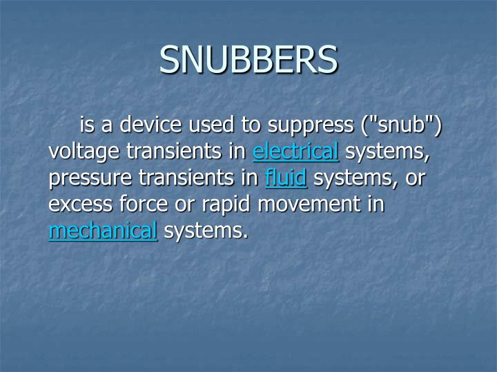
SNUBBERS. is a device used to suppress ("snub") voltage transients in electrical systems, pressure transients in fluid systems, or excess force or rapid movement in mechanical systems.

E N D
SNUBBERS is a device used to suppress ("snub") voltage transients in electrical systems, pressure transients in fluid systems, or excess force or rapid movement in mechanical systems.
Snubbers are frequently used in electrical systems with an inductive load where the sudden interruption of current flow often leads to a sharp rise in voltage across the device creating the interruption. This sharp rise in voltage is a transient and can damage and lead to failure of the controlling device. A spark is likely to be generated (arcing), which can cause electromagnetic interference in other circuits. The snubber prevents this undesired voltage by conducting transient current around the device. RC snubbers Electrical systems
Requirements: • The voltage & current remain must remain within the safe operating area (SOA) of the device. • To keep the rate of change of the device voltage & current low enough to provide correct & reliable operation during switch transition. • To limit the dissipation that occurs in the device during switching.
Function of Snubber Circuits • • Protect semiconductor devices by: • • Limiting device voltages during turn-off transients • • Limiting device currents during turn-on transients • • Limiting the rate-of-rise (didt) of currents through the • semiconductor device at device turn-on • • Limiting the rate-of-rise (dvdt) of voltages across the • semiconductor device at device turn-off • • Shaping the switching trajectory of the device as it • turns on/off
2 basic kinds of snubbers: • To control the rate of rise of the switch voltage. (turn-off snubbers) • The second controls the rate of rise of switch current. (turn-on snubbers) Both use small energy storage elements – a capacitor and inductor.
Turn on Snubber: • A snubber inductor is placed in series with the transistor. (Ls) is used to limit the transistor current.
Practical Turn-on snubber: • We need to add a components to allow the transistor to survive the switch transition. • If nothing were added to the ckt., the transistor would receive an impulse of voltage when it turned off, because the inductor current would be forced to change in a very short time. • Solution: • We add resistor to provide alternative path for the inductor current when the transistor turns off. • We add diode to keep the resistor from conducting during the turn-on transition. Note: the resistance Rs must be large enough to completely discharge Ls during the off-state. To minimize the transistor’s voltage stress, it shld. Not be made any larger thatn necessary.
A More Practical Snubber: • A capacitor by itself is not a sufficient turn-off snubber because when the transistor is turned on again, Cs will discharge through Q. the resulting transistor current can be very large and lead to failure . • Solution: • We add a resistor to limit the discharge current when the transistor is turned on. • We add a diode to allow charging current to bypass the resistor during the turn-off transition.
Tradeoff • Is necessary in determining the value of Rs. It must be small enough to ensure the capacitor is fully discharged during the shortest time that Q might be on but large enough to prevent the discharge current from exceeding the transistor rating.
DISSIPATION IN SNUBBER CIRCUITS • At the beginning of a turn-on/turn-off transition, the energy storage element in the corresponding snubber ckt. Contains no stored energy. When the transition is over, however, the element is left with a nonzero value of stored energy. This energy is dissipated during the next switch transition.
RC SNUBBER • A simple snubber comprising a small resistor (R) in series with a small capacitor (C) is often used. This combination can be used to suppress the rapid rise in voltage across a thyristor. • are also often used to prevent arcing across the contacts of relays and switches and the electrical interference and welding/sticking of the contacts that can occur.
Types of Snubber Circuits • 1. Unpolarized series R-C snubbers • • Used to protect diodes and thyristors • 2. Polarized R-C snubbers • • Used as turn-off snubbers to shape the turn-on switching • trajectory of controlled switches. • • Used as overvoltage snubbers to clamp voltages applied to • controlled switches to safe values. • • Limit dvdt during device turn-off • 3. Polarized L-R snubbers • • Used as turn-on snubbers to shapte the turn-off switching • trajectory of controlled switches. • • Limit didt during device turn-on
END THANKYOU!!! FOR LISTENING…