Download

1 / 57
570 likes | 690 Views
Human Generated Power for B9 Better Water Maker. P13417. Introduction to the Team. Table of Contents. Project Overview Problem Statement Customer Needs Specifications Current Design Testing Preliminary Concepts Concept Selection Conclusions. Project Overview. B9 Plastics:

E N D
Table of Contents • Project Overview • Problem Statement • Customer Needs • Specifications • Current Design • Testing • Preliminary Concepts • Concept Selection • Conclusions
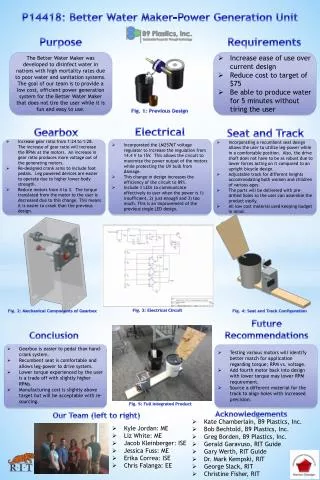
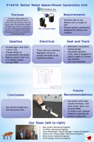
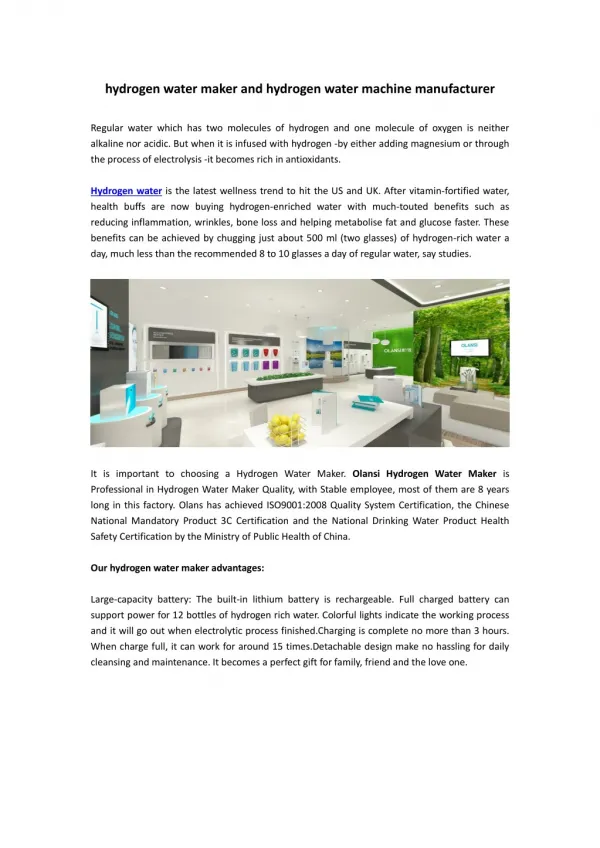
Project Overview • B9 Plastics: A not for profit organization dedicated to social and environmental improvement through the use of certain materials (plastics). • Better Water Maker (BWM): A water treatment device used in the developing world to kill water microbes by using ultraviolet light. The device uses a human powered crank to generate power for the device at 12v.
Problem Statement • Our project, in conjunction with B9 plastics, is to redesign the power generator to ease the use of this device for women and children. The current design seems to be too physically demanding to maintain the proper power output for the time required to cleanse a moderate amount of water (over 1 gallon).
Concept Selection • New Gear Box • To obtain better gear ratio • Maintain/reuse all electrical work • Motors still experience same input rpms • New Motors • To obtain better gear ratio • Ease cost • Reduce losses due to friction • Significant increase in total lifetime Goal: Each proposal is to decrease input crank rpms *Both proposals include using legs/feet to pedal generator
Maximum allowable leg force required to power generator • Current generator requires 50in*lbs of torque to maintain required rpms • Equates to 9 lbf at crank arm handle which is 40% of maximum arm force of women (21 lbf) • Maximum leg force of average woman is 63 lbf • Allowable force = 40% of 63 lbf • 25 lbf experienced at crank arm handle (pedal)
New Gear Box Comparison New Gear Box Design Current
Current Design • Large Gear with 9 lbf applied to crank handle Ultimate Strength of “Harbec plastic” is 10,700psi
Proposed Design • Large Gear with 25 lbf applied to crank handle (pedal)
Current Crank Arm • 9 lbf applied
Current Crank Arm • 25 lbf applied
Gear Small Radius • 25 lbf applied to crank arm pedal
Current Motor • Mabuchi RS-555PC • Short lifetime • <6000 hours
New Motor • CF Motor RS-390PH • Brushed motor • Longer lifetime • More efficient • 4 of these motors in a configuration with 2 parallel • Desired voltage/power of 12 V/17 W • Desired RPMs of ~1650
Proposed Changes • Reverse diode across inductor • Incentive: circuit integrity • Currently the circuit contains an inductor near the input that has no alternative current path, should the transistor in series with it turn off • Adding a reverse diode in parallel with this inductor ensures a discharge path for this current • Replacement of potentiometer by low tolerance resistors • Incentive: cost • The current circuit uses an op-amp comparator and a 5V reference to control powering of a power LED • This LED turns on when a sufficient voltage is generated (>12 V)
Pump Circuit • Existing Pump Circuit • Accepts a variable input voltage • 12 V/19 W required to power the ballast and pump • After 10 seconds, pump will activate, moves water through device
Proposed Changes • Smoothing RC network (“electrical flywheel”) • Incentive: efficiency, easiness of use • Add smoothing smoothing RC network for charge storage • The time allowed for not cranking the generator and keeping the pump on was decided to be 1.0 seconds • Time constant • This time constant can be achieved with a 100 µF effective capacitance and a 135 kΩ effective resistance.
Seat Design Proposal • Preliminary concepts:


![CONVERGENCE BiII [B9-2005]](https://cdn1.slideserve.com/1716871/convergence-biii-b9-2005-dt.jpg)