Download
1 / 49
490 likes | 623 Views
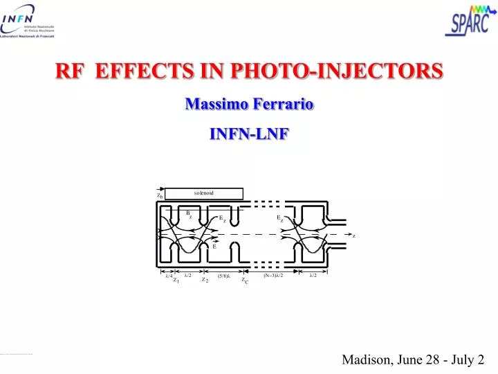
RF EFFECTS IN PHOTO-INJECTORS Massimo Ferrario INFN-LNF. Madison, June 28 - July 2. Trapping a plane wave in a box Longitudinal RF effects Transverse RF effects.

E N D
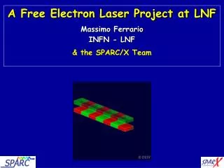
RF EFFECTS IN PHOTO-INJECTORS Massimo Ferrario INFN-LNF Madison, June 28 - July 2
Trapping a plane wave in a box • Longitudinal RF effects • Transverse RF effects
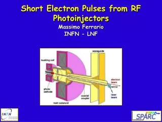
The solutions to the electromagnetic wave equation in free space are transversely polarized waves (the electric field is transverse to the propagation vector) that have phase velocity c, the speed of light. These properties are problematic from the viewpoint of charged particle acceleration, because in order for a charged particle to absorb energy from an applied electric force, the motion of the charged particle must have a component parallel to the electric field: If the motion of the particle in an accelerating wave is rectilinear in the z-direction, the electric field must be rotated to have a longitudinal component in order for acceleration to occur. This can be accomplished by using a smooth-walled waveguide.
Let us consider a charge co-propagating in the z direction with a wave having a longitudinal component Ez the particle experiences an accelerating voltage The energy gain depends on the spatial pattern of the field and on the phase relation (phase slippage) The wave is syncronous when
Interaction with a plane wave: particle at rest B E Non relativistic approx: x z
B E Interaction with a plane wave: particle/wave co-propagating using
Wave front x z Interaction with a plane wave with an angle Not yet suitable
x z Plane wave reflected by a perfectly conducting plane In the plane xz the field is given by the superposition of the incident and reflected wave
x Taking into account the boundary conditions the longitudinal component of the field becomes z-TW pattern x-SW pattern Notice that Not only on the conductor:
We can confine the plane wave with a second parallel conducting plane located where Ez = 0 so that boundary condition are fulfilled x z This is a guided plane wave also called TMn mode n indicates the number of half wavelength between the two plates
Not all angles q are possible for a given distance a between the two plates ==> If a would be then Implying a normal incidence and no propagation Cut-Off condition:Only waves with l < lc = 2a can propagate
The phase velocity is given by > c if l < lc Im if l > lc The previous relation is identical to That is a dispersion relation
We must slow down the wave propagation In order to slow down the waves we have to load the cavity by introducing some periodic obstacle into it
With this general form of the solution, the field can be viewed as the sum of many wave components, which are termed spatial harmonics, having different longitudinal wave-numbers , and thus different phase velocities .
Beam Dinamycs in Photo-Injectors: RF effects
Micro-Bunch Production with rf photo-injectors • Luca Serafini (INFN - Milan) • Workshop on 2nd Generation Plasma Accelerators, • Kardamyli, Greece, June 1995
Longitudinal RF effects Eo peak accelerating field jophase as the particle lives the cathode surface Let us try to compute the energy gain for a particle with b=0
Impulsive Approximation to Electron Capture: assuming a constant electric field nearby the cathode surface (z~0) The longitudinal equation of motion becomes assuming giving
Introducing the dimensionless vector potential amplitude and We obtain Wich has an asymptotic behavior
Defining the phase slippage as It has an asymptotic behavior given by Which has a minimum at j = p/2 that is also the phase of maximum acceleration and it is small if a > 1/2 ( ex: n = 2.856 GHz, Eo = 100 MV/m ==> a=1.63 )
Assuming that the photo-electrons are emitted from the cathode directly at the speed of light, at a phase equal to the asymptotic phase, the energy gain is simply given by where the non relativistic part of the motion has been considered equivalent to a new definition of the injection phase
Phase Compression Defining as the phase separation between two different photo-electrons emitted at two launching pahse, their asimptotical distance will be given by: By defining the relative change in phase distance between the two electrons
The final length of the emitted electron bunch will be given by: The injection phase jo which corresponds to an asymptotic phase j = p/2 is the treshold below which we have Phase Compression and above which Phase Expansion. For injection phases close to jo = 0 the Compression can produce bunching even down to a factor 4
Energy Spread At the gun exit we have substituting II order expansion around <j>
giving We are interested in the phase and So that Or in terms of the rms quantity
Electron phase, energy at gun exit (2nd iris): simulations vs. analytical
Exercise: show that the Longitudinal emittance is given by where In particular for a Gaussian distribution show that
The fields that accelerate the charged particles in a radio-frequency linac cavity also give rise to transverse components of the Lorentz force that deflect the particles. Transverse RF effects Assuming cylindrical symmetry, transverse electromagnetic fields in an accelerating structure can be obtained by a linear expansion near the axis of the Maxwell equations:
The radial component of the Lorentz force becomes Thus in the ultra-relativistic limit , the net radial Lorentz force is simply proportional to the total z-derivative of the accelerating field.
Tc Tnc Symmetric structure If we integrate the radial forces through an isolated electromagnetic structure with constant velocity and radial offset we obtain for the full momentum transfer This result explicitly shows that the sum of all inward and outward impulses applied within the structure cancel for an ultra-relativistic particle traversing a cylindrically symmetric structure.
Anti-symmetric structure z Tc Texit But in the last half cell This represents a defocussing kick when 0 < j < p Thus it usually will be necessary to focus the beam immediately after leaving the cavity
Transverse RF emittance Rewriting pr in Cartesian coordinates: It gives the phase space distribution: a collection of lines with different slopes corresponding to different j The normalized transverse emittance is: By inserting px we obtain
writing and assuming that Dj is small so that one obtains from:
It has a minimum for <f>=p/2 Away from the minimum we have
For a Gaussian beam distriution The rms quantitie are And the emittance becomes:
Exercise: show that for a uniform distribution in a cylinder of radius a and length L, the relevant moments for the distribution are: And the transverse emittance is:
Tc Tnc Symmetric structure Second order transverse focusing in electromagnetic accelerating fields if one relaxes the assumptions of constant velocity and offset from the design orbit and examines the effects of the alternating gradient forces, one finds that they give rise to a second order secular focusing force
The approximation we will employ here assumes that the motion can be broken down into two components, one which contains the small amplitude fast oscillatory motion (the perturbed part of the motion), and the other that contains the slowly varying or secular, large amplitude variations in the trajectory.
The oscillatory component is analyzed by making the approximation that the offset x=xsec is constant over an oscillation so that: Which has a simple solution The original equation becomes
The last step is to convert it into an averaged expression over a period, that gives the behavior of the secular component of the motion
Simple Fourier decomposition of the on-axis solution then gives the useful form With this general form of the solution, the field can be viewed as the sum of many wave components, which are termed spatial harmonics, having different longitudinal wave-numbers , and thus different phase velocities .
we assume the n=0 spatial harmonic is synchronous with the relativistic particle motion, or For a particle located at a phase j with respect to maximum acceleration, we have
If the energy variation is ignorably small over a period, then one may proceed to find the secular radial equation of motion by averaging the lowest order oscillatory motion given by the previous equation over a structure period. witch has a steady-state solution
Substitution of the value of and averaging, we have This radial focusing force, like that derived from the solenoid provides equal focusing in both x and y, which is second order in applied field strength . In the case of the solenoid, the net radial force is second order due to the accompanying rotation, while in the present case it is of second order because of the fast radial oscillatory motion due to alternating gradient focusing
represents a sum over all spatial harmonics that contribute to the alternating gradient force, and is equal to 1 for a pure harmonic standing wave.Note that the synchronous harmonic (n=0) does not contribute to the first or second order force in the ultra-relativistic limit, so that h=0 for a pure forward traveling wave (ao=1, all other an vanishing). the alternating gradient focusing effect arises from the existence of non-synchronous spatial harmonics
Because we have kept the energy constant, we have not kept the effects of adiabatic damping in the equation of motion. Acceleration can be taken into account by use of the damping term. Because the focusing is symmetric, the resulting equations of motion in x, y and r are all equivalent, and are of the form