Download
1 / 31
310 likes | 498 Views
Electromagnetic Radiation Principles.

E N D
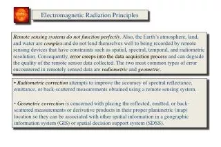
Electromagnetic Radiation Principles Remote sensing systems do not function perfectly. Also, the Earth’s atmosphere, land, and water are complex and do not lend themselves well to being recorded by remote sensing devices that have constraints such as spatial, spectral, temporal, and radiometric resolution. Consequently, error creeps into the data acquisition process and can degrade the quality of the remote sensor data collected. The two most common types of error encountered in remotely sensed data are radiometric and geometric. • Radiometriccorrection attempts to improve the accuracy of spectral reflectance, emittance, or back-scattered measurements obtained using a remote sensing system. • Geometriccorrection is concerned with placing the reflected, emitted, or back-scattered measurements or derivative products in their proper planimetric (map) location so they can be associated with other spatial information in a geographic information system (GIS) or spatial decision support system (SDSS).
Electromagnetic Radiation Principles Radiometric and geometric correction of remotely sensed data are normally referred to as preprocessing operations because they are performed prior to information extraction. Image preprocessing hopefully produces a corrected image that is as close as possible, both radiometrically and geometrically, to the true radiant energy and spatial characteristics of the study area at the time of data collection. Internal and external errors must be identified to correct the remotely sensed data:
Electromagnetic Energy Interactions • Energy recorded by remote sensing systems undergoes fundamental interactions that should be understood to properly preprocess and interpret remotely sensed data. For example, if the energy being remotely sensed comes from the Sun, the energy: • is radiated by atomic particles at the source (the Sun), • travels through the vacuum of space at the speed of light, • interacts with the Earth’s atmosphere, • interacts with the Earth’s surface, • interacts with the Earth’s atmosphere once again, and • finally reaches the remote sensor, where it interacts with various • optics, filters, film emulsions, or detectors.
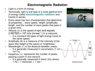
Wave Model of Electromagnetic Radiation In the 1860s, James Clerk Maxwell (1831–1879) conceptualized electromagnetic radiation (EMR) as an electromagnetic wave that travels through space at the speed of light,c, which is 3 x 10⁸ meters per second (hereafter referred to as m s-1) or 186,282.03 miles s-1. A useful relation for quick calculations is that light travels about 1 ft per nanosecond (10-9 s). Theelectromagnetic wave consists of two fluctuating fields—one electric and the other magnetic. The two vectors are at right angles (orthogonal) to one another, and both are perpendicular to the direction of travel.
Sources of Electromagnetic Energy • Thermonuclear fusion taking place on the surface of the Sun yields a continuous spectrum of electromagnetic energy. The 5770 – 6000 kelvin (K) temperature of this process produces a large amount of relatively short wavelength energy that travels through the vacuum of space at the speed of light. Some of this energy is intercepted by the Earth, where it interacts with the atmosphere and surface materials. The Earth reflects some of the energy directly back out to space or it may absorb the short wavelength energy and then re-emit it at a longer wavelength.
Solar and Heliospheric Observatory (SOHO) Image of the Sun Obtained on September 14, 1999
Blackbody Radiation Curves Blackbody radiation curves for several objects including the Sun and the Earth which approximate 6,000 K and 300 K blackbodies, respectively. The area under each curve may be summed to compute the total radiant energy (Ml) exiting each object. Thus, the Sun produces more radiant exitance than the Earth because its temperature is greater. As the temperature of an object increases, its dominant wavelength (lmax) shifts toward the shorter wavelengths of the spectrum.
Wien’s Displacement Law • In addition to computing the total amount of energy exiting a theoretical blackbody such as the Sun, we can determine its dominant wavelength(lmax) based on Wien’s displacement law: • where k is a constant equaling 2898 mm K, and T is the absolute temperature in kelvin. Therefore, as the Sun approximates a 6000 K blackbody, its dominant wavelength (lmax) is 0.48 mm:
Radiant Intensity of the Sun The Sun approximates a 6000 K blackbody with a dominant wavelength of 0.48 m (green light). Earth approximates a 300 K blackbody with a dominant wavelength of 9.66 m. The 6000 K Sun produces 41% of its energy in the visible region from 0.4 - 0.7 m (blue, green, and red light). The other 59% of the energy is in wavelengths shorter than blue light (<0.4 m) and longer than red light (>0.7 m). Eyes are only sensitive to light from the 0.4 to 0.7 m. Remote sensor detectors can be made sensitive to energy in the non-visible regions of the spectrum.
Radiometric Quantities All objects above absolute zero (–273°C or 0 K) emit electromagnetic energy, including water, soil, rock, vegetation, and the surface of the Sun. The Sun represents the initial source of most of the electromagnetic energy recorded by remote sensing systems (except RADAR, LIDAR, and SONAR). We may think of the Sun as a 5770 – 6000 K blackbody (a theoretical construct that absorbs and radiates energy at the maximum possible rate per unit area at each wavelength (l) for a given temperature). The total emitted radiation from a blackbody (Ml) measured in watts per m2 is proportional to the fourth power of its absolute temperature (T) measured in kelvin (K). This is known as the Stefan-Boltzmann law and is expressed as: where σis the Stefan-Boltzmann constant, 5.66697 x 10⁻⁸ W m-2 K-4.
Quantum Theory of EMR Niels Bohr (1885–1962) and Max Planck recognized the discrete nature of exchanges of radiant energy and proposed the quantum theory of electromagnetic radiation. This theory states that energy is transferred in discrete packets called quanta or photons. The relationship between the frequency of radiation expressed by wave theory and the quantum is: where Q is the energy of a quantum measured in joules, h is the Planck constant (6.626 10-34 J s), and n is the frequency of the radiation.
Atmospheric Refraction Refraction in three nonturbulent atmospheric layers. The incident energy is bent from its normal trajectory as it travels from one atmospheric layer to another. Snell’s law can be used to predict how much bending will take place, based on a knowledge of the angle of incidence (q) and the index of refraction of each atmospheric level, n1, n2, n3.
Index of Refraction • The index of refraction (n) is a measure of the optical density of a substance. This index is the ratio of the speed of light in a vacuum, c, to the speed of light in a substance such as the atmosphere or water, cn: • The speed of light in a substance can never reach the speed of light in a vacuum. Therefore, its index of refraction must always be >1. For example, the index of refraction for the atmosphere is 1.0002926 and 1.33 for water. Light travels more slowly through water because of water’s higher density.
Snell’s Law • Refraction can be described by Snell’s law, which states that for a given frequency of light (we must use frequency since, unlike wavelength, it does not change when the speed of light changes), the product of the index of refraction and the sine of the angle between the ray and a line normal to the interface is constant: • From the accompanying figure, we can see that a nonturbulent atmosphere can be thought of as a series of layers of gases, each with a slightly different density. Anytime energy is propagated through the atmosphere for any appreciable distance at any angle other than vertical, refraction occurs.
Snell’s Law • The amount of refraction is a function of the angle made with the vertical (q), the distance involved (in the atmosphere the greater the distance, the more changes in density), and the density of the air involved (air is usually more dense near sea level). Serious errors in location due to refraction can occur in images formed from energy detected at high altitudes or at acute angles. However, these location errors are predictable by Snell’s law and thus can be removed. Notice that • Therefore, if one knows the index of refraction of medium n1 and n2 and the angle of incidence of the energy to medium n1, it is possible to predict the amount of refraction that will take place(sinq2) in medium n2 using trigonometric relationships. It is useful to note, however, that most image analysts never concern themselves with computing the index of refraction.
Atmospheric Layers and Constituents Major subdivisions of the atmosphere and the types of molecules and aerosols found in each layer.
Rayleigh Scattering The intensity of Rayleigh scattering varies inversely with the fourth power of the wavelength (-4).
Rayleigh Scattering The approximate amount of Rayleigh scattering in the atmosphere in optical wavelengths (0.4 – 0.7 mm) may be computed using the Rayleigh scattering cross-section (tm) algorithm: where n = refractive index, N = number of air molecules per unit volume, and l = wavelength. The amount of scattering is inversely related to the fourth power of the radiation’s wavelength.
Atmospheric Scattering • Type of scattering is a function of: • the wavelength of the incident radiant energy, and • the size of the gas molecule, dust particle, and/or water vapor droplet encountered.
Absorption of the Sun's Incident Electromagnetic Energy in the Region from 0.1 to 30 mm by Various Atmospheric Gases window Atmospheric Absorption
a) The absorption of the Sun’s incident electromagnetic energy in the region from 0.1 to 30 mm by various atmospheric gases. The first four graphs depict the absorption characteristics of N2O, O2 and O3, CO2, and H2O, while the final graphic depicts the cumulative result of all these constituents being in the atmosphere at one time. The atmosphere essentially “closes down” in certain portions of the spectrum while “atmospheric windows” exist in other regions that transmit incident energy effectively to the ground. It is within these windows that remote sensing systems must function. b) The combined effects of atmospheric absorption, scattering, and reflectance reduce the amount of solar irradiance reaching the Earth’s surface at sea level. Nitrous oxide
Typical spectral reflectance curves for urban–suburban phenomena in the region 0.4 – 0.9 mm.
Terrain Energy-Matter Interactions The time rate of flow of energy onto, off of, or through a surface is called radiant flux (F) and is measured in watts (W). The characteristics of the radiant flux and what happens to it as it interacts with the Earth’s surface is of critical importance in remote sensing. In fact, this is the fundamental focus of much remote sensing research. By carefully monitoring the exact nature of the incoming (incident) radiant flux in selective wavelengths and how it interacts with the terrain, it is possible to learn important information about the terrain.
Terrain Energy-Matter Interactions Radiometric quantities have been identified that allow analysts to keep a careful record of the incident and exiting radiant flux. We begin with the simpleradiation budget equation, which states that the total amount of radiant flux in specific wavelengths (l) incident to the terrain ( ) must be accounted for by evaluating the amount of radiant flux reflected from the surface ( ), the amount of radiant flux absorbed by the surface ( ), and the amount of radiant flux transmitted through the surface ( ):
Hemispherical Reflectance, Absorptance, and Transmittance • The Hemispherical reflectance (rl) is defined as the dimensionless ratio of the radiant flux reflected from a surface to the radiant flux incident to it: • Hemispherical transmittance (tl) is defined as the dimensionless ratio of the radiant flux transmitted through a surface to the radiant flux incident to it: • Hemispherical absorptance (al) is defined by the dimensionless relationship:
Hemispherical Reflectance, Absorptance, and Transmittance • These radiometric quantities are useful for producing general statements about the spectral reflectance, absorptance, and transmittance characteristics of terrain features. In fact, if we take the simple hemispherical reflectance equation and multiply it by 100, we obtain an expression for percent reflectance (): • This quantity is used in remote sensing research to describe the general spectral reflectance characteristics of various phenomena.
Radiant Flux Density • The concept of radiant flux density for an area on the surface of the Earth. • Irradiance is a measure of the amount of radiant flux incident upon a surface per unit area of the surface measured in watts m-2. • Exitance is a measure of the amount of radiant flux leaving a surface per unit area of the surface measured in watts m-2.
Irradiance and Exitance The amount of radiant flux incident upon a surface per unit area of that surface is called Irradiance(E), where: • The amount of radiant flux leaving per unit area of the plane surface is called Exitance(M). • Both quantities are measured in watts per meter squared (W m-2).
Radiance Radiance (L) is the radiant flux per unit solid angle leaving an extended source in a given direction per unit projected source area in that direction and is measured in watts per meter squared per steradian (W m-2 sr-1 ). We are only interested in the radiant flux in certain wavelengths (F) leaving the projected source area (A) within a certain direction () and solid angle ():
The concept of radiance leaving a specific projected source area on the ground, in a specific direction, and within a specific solid angle.