Download
1 / 39
440 likes | 820 Views
Chapter 8 - Feedback. 1 - Desensitize The Gain 2 - Reduce Nonlinear Distortions 3 - Reduce The Effect of Noise 4 – Control The Input And Output Impedances 5 – Extend The Bandwidth Of The Amplifier. The General Feedback Structure.

E N D
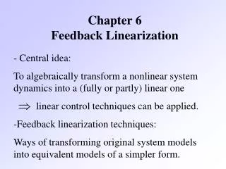
Chapter 8 - Feedback 1 - Desensitize The Gain 2 - Reduce Nonlinear Distortions 3 - Reduce The Effect of Noise 4 – Control The Input And Output Impedances 5 – Extend The Bandwidth Of The Amplifier
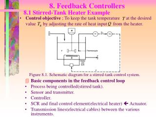
The General Feedback Structure Basic structure of a feedback amplifier. To make it general, the figure shows signal flow as opposed to voltages or currents (i.e., signals can be either current or voltage). The open-loop amplifier has gain A xo = A*xi Output is fed back through a feedback network which produces a sample (xf) of the output (xo) xf = bxo Where b is called the feedback factor The input to the amplifier is xi = xs – xf (the subtraction makes feedback negative) Implicit to the above analysis is that neither the feedback block nor the load affect the amplifier’s gain (A). This not generally true and so we will later see how to deal with it. The overall gain (closed-loop gain) can be solved to be: Ab is called the loop gain 1+Ab is called the “amount of feedback”
Finding Loop Gain Generally, we can find the loop gain with the following steps: • Break the feedback loop anywhere (at the output in the ex. below) • Zero out the input signal xs • Apply a test signal to the input of the feedback circuit • Solve for the resulting signal xo at the output If xo is a voltage signal, xtst is a voltage and measure the open-circuit voltage If xo is a current signal, xtst is a current and measure the short-circuit current • The negative sign comes from the fact that we are apply negative feedback
Negative Feedback Properties • Negative feedback takes a sample of the output signal and applies it to the input to get several desirable properties. In amplifiers, negative feedback can be applied to get the following properties • –Desensitized gain – gain less sensitive to circuit component variations • –Reduce nonlinear distortion – output proportional to input (constant gain independent of signal level) • –Reduce effect of noise • –Control input and output impedances – by applying appropriate feedback topologies • –Extend bandwidth of amplifier • These properties can be achieved by trading off gain
Gain Desensitivity Feedback can be used to desensitize the closed-loop gain to variations in the basic amplifier. Let’s see how. Assume beta is constant. Taking differentials of the closed-loop gain equation gives… Divide by Af This result shows the effects of variations in A on Af is mitigated by the feedback amount. 1+Abeta is also called the desensitivity amount We will see through examples that feedback also affects the input and resistance of the amplifier (increases Ri and decreases Ro by 1+Abeta factor)
Bandwidth Extension We’ve mentioned several times in the past that we can trade gain for bandwidth. Finally, we see how to do so with feedback… Consider an amplifier with a high-frequency response characterized by a single pole and the expression: Apply negative feedback beta and the resulting closed-loop gain is: • Notice that the midband gain reduces by (1+AMbeta) while the 3-dB roll-off frequency increases by (1+AMbeta)
Basic Feedback Topologies series-shunt Depending on the input signal (voltage or current) to be amplified and form of the output (voltage or current), amplifiers can be classified into four categories. Depending on the amplifier category, one of four types of feedback structures should be used (series-shunt, series-series, shunt-shunt, or shunt-series) Voltage amplifier – voltage-controlled voltage source Requires high input impedance, low output impedance Use series-shunt feedback (voltage-voltage feedback) Current amplifier – current-controlled current source Use shunt-series feedback (current-current feedback) Transconductance amplifier – voltage-controlled current source Use series-series feedback (current-voltage feedback) Transimpedance amplifier – current-controlled voltage source Use shunt-shunt feedback (voltage-current feedback) shunt-series series-series shunt-shunt
Examples of the Four Types of Amplifiers • Shown above are simple examples of the four types of amplifiers. Often, these amplifiers alone do not have good performance (high output impedance, low gain, etc.) and are augmented by additional amplifier stages (see below) or different configurations (e.g., cascoding).
Series-Shunt Feedback Amplifier(Voltage-Voltage Feedback) Samples the output voltage and returns a feedback voltage signal Ideal feedback network has infinite input impedance and zero output resistance Find the closed-loop gain and input resistance The output resistance can be found by applying a test voltage to the output So, increases input resistance and reduces output resistance makes amplifier closer to ideal VCVS
The Series-Shunt Feedback Amplifier The Ideal Situation • The series-shunt feedback amplifier: • ideal structure; • equivalent circuit.
Series-Series Feedback Amplifier(Current-Voltage Feedback) For a transconductance amplifier (voltage input, current output), we must apply the appropriate feedback circuit Sense the output current and feedback a voltage signal. So, the feedback current is a transimpedance block that converts the current signal into a voltage. To solve for the loop gain: Break the feedback, short out the break in the current sense and applying a test current To solve for Rif and Rof Apply a test voltage Vtst across O and O’
Shunt-Shunt Feedback Amplifier(Voltage-Current Feedback • When voltage-current FB is applied to a transimpedance amplifier, output voltage is sensed and current is subtracted from the input • The gain stage has some resistance • The feedback stage is a transconductor • Input and output resistances (Rif and Rof) follow the same form as before based on values for A and beta
Shunt-Series Feedback Amplifier(Current-Current Feedback) • A current-current FB circuit is used for current amplifiers • For the b circuit – input resistance should be low and output resistance be high • A circuit example is shown • RS and RF constitute the FB circuit • RS should be small and RF large • The same steps can be taken to solve for A, Abeta, Af, Rif, and Rof • Remember that both A and b circuits are current controlled current sources
The General Feedback Structure MATLAB / SIMULINK Anyone interested to put together an Introduction to MATLAB / Simulink PowerPoint Presentation plus some examples?
The General Feedback Structure Exercise 8.1
The General Feedback Structure Exercise 8.1
Some Properties of Negative Feedback Gain Desensitivity
Some Properties of Negative Feedback Bandwidth Extension
Some Properties of Negative Feedback Noise Reduction, Reduction of Nonlinear Distortion Read and discuss in class
The Shunt-Series Feedback Amplifier Example 8.1
The Shunt-Series Feedback Amplifier Example 8.1
The Shunt-Series Feedback Amplifier Example 8.1
The Series-Shunt Feedback Amplifier Exercise 8.5
The Series-Shunt Feedback Amplifier Example 8.2
The Series-Shunt Feedback Amplifier Exercise 8.6
The Shunt-Shunt Feedback Amplifier Exercise 8.3
The Shunt-Shunt Feedback Amplifier Example 8.4
The Shunt-Shunt Feedback Amplifier Example 8.4
The Shunt-Shunt Feedback Amplifier Exercise 8.7
Determining The Loop Gain Exercise 8.8-9
The Stability Problem The Stability Problem and Margins Nyquist Closed-Loop Transfer Function Root-Locus Bode
The Stability Problem Nyquist Closed-Loop Transfer Function Root-Locus Bode
Stability Study Using Bode Plots Bode plot for loop gain Abeta • Gain margin is an indication of excess gain before instability • Phase margin is an indication of excess phase before -180° phase shift at unity gain
The Stability Problem Exercise 8.10
Effect of Feedback on the Amplifier Poles Exercise 8.11