Download
1 / 38
460 likes | 741 Views
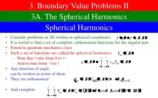
Electrostatic Boundary value problems. Sandra Cruz-Pol, Ph. D. INEL 4151 ch6 Electromagnetics I ECE UPRM Mayagüez, PR. Last Chapters: we knew either V or charge distribution, to find E,D. NOW: Only know values of V or Q at some places (boundaries). Some applications.

E N D
Electrostatic Boundary value problems Sandra Cruz-Pol, Ph. D. INEL 4151 ch6 Electromagnetics I ECE UPRM Mayagüez, PR
Last Chapters: we knew either V or charge distribution, to find E,D.NOW: Only know values of V or Q at some places (boundaries).
Some applications • Microstrip lines capacitance • Microstrip disk for microwave equipment
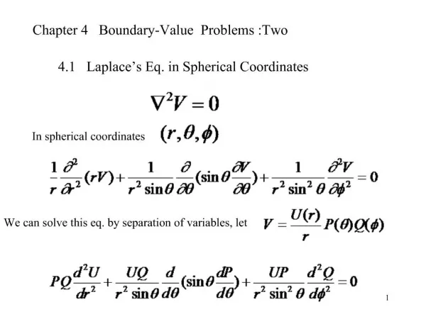
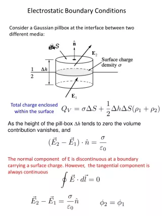
To find E, we will use: • Poisson’s equation: • Laplace’s equation: (if charge-free) They can be derived from Gauss’s Law
Depending on the geometry: We use appropriate coordinates: cartesian: cylindrical: spherical:
Procedure for solving eqs. • Choose Laplace (if no charge) or Poisson • Solve by Integration if one variable or by • Separation of variables if many variables • Apply B.C. • Find V, then E=-DV, D=eE, J=sE • Also, if necessary:
P.E. 6.1 In a 1-dimensional device, the charge density is given by If E=0 at x=0 and V=0 at x=a, find V and E. Evaluating B.C.
45o P.E. 6.3 two conducting plates of size 1x5m are inclined at 45o to each other with a gap of width 4mm separating them as shown below. Find approximate charge per plate if plates are kept at 50V potential difference and medium between them has permittivity of 1.5 Applying B.C. V(0)=0, V(fo=45)=Vo=50 1m
45o P.E. 6.3 two conducting plates of size 1x5m are inclined at 45o to each other with a gap of width 4mm separating them as shown below. permittivity of 1.5 Applying B.C. V(0)=0, V(fo=45)=Vo=50 b a
45o detail b a
P.E. 6.5 Determine the potential function for the region inside the rectangular trough of infinite length whose cross section is shown. • The potential V depends on x and y. • Vo=100V, b=2a=2m, find V and E at: • (x, y)=(a, a/2) • (x, y)=(3a/2, a/4) y V=Vo a V=0 V=0 x b V=0
P.E. 6.5 (cont.) Since it’s 2 variables, use Separation of Variables y V=Vo a V=0 V=0 x b V=0
Let’s examine 3 Possible Cases • l=0 • l<0 • l>0
Case A: If l=o y V=Vo a V=0 V=0 x b V=0 This is a trivial solution, therefore l cannot be equal to zero.
Case B: l<o This is another trivial solution, therefore l cannot be equal to zero.
Case C: l>o By superposition, the combination is also a solution:
Cont. B.C. at y=a If we multiply by sin factor and integrate on x: Orthogonality property of sine and cosine:
V=Vo V=0 Equipotential lines Flux lines V=0
Find V(a,a/2) where Vo=100V, b=2a=2m V=Vo V=0 Equipotential lines Flux lines V=0
Resistance • If the cross section of a conductor is not uniform we need to integrate: • Solve Laplace eq. to find V • Then find E from its differential • And substitute in the above equation
P.E. 6.8 find Resistance of disk of radius b and central hole of radius a. b a t
Capacitance • Is defined as the ratio of the charge on one of the plates to the potential difference between the plates: • Assume Q and find V (Gauss or Coulomb) • Assume V and find Q (Laplace) • And substitute E in the equation.
Capacitance • Parallel plate • Coaxial • Spherical
Parallel plate Capacitor Plate area, S • Charge Q and –Q • or Dielectric, e
Plate area, S - - - - - - Dielectric, e + + + - + + c - - Coaxial Capacitor • Charge +Q & -Q
Spherical Capacitor • Charge +Q & -Q
What is the Earth's charge? The Earth is electrically charged and acts as a spherical capacitor. The Earth has a net negative charge of about a million coulombs, while an equal and positive charge resides in the atmosphere. • The electrical resistivity of the atmosphere decreases with height to an altitude of about 48 kilometres (km), where the resistivity becomes more-or-less constant. This region is known as the electrosphere. There is about a 300 000 volt (V) potential difference between the Earth's surface and the electrosphere, which gives an average electric field strength of about 6 V/metre (m) throughout the atmosphere. Near the surface, the fine-weather electric field strength is about 100 V/m.
Capacitors connection • Series • Parallel
Resistance • Recall that: • Multiplying, we obtain the Relaxation Time: • Solving for R, we obtain it in terms of C:
P.E. 6.9 s1 • A coaxial cable contains an insulating material of s1 in its upper half and another material with s2 in its lower half. Radius of central wire is a and of the sheath is b. Find the leakage resistance of length L. They are connected in parallel s2
P.E. 6.10a e1 e2 • Two concentric spherical capacitors with e1r=2.5 in its outer half and another material with e2r=3.5 in its inner half. The inner radius is a=1mm, b=3mm and c=2mm . Find their C. We have two capacitors in series: c
P.E. 6.10b e1 • Two spherical capacitors with e1r=2.5 in its upper half and another material with e2r=3.5 in its lower half. Inner radius is a=1mm and b=3mm. Find their C. We have two capacitors in parallel: e2
Method of Images • Whenever the is a charge in the presence of a conductor. The conductor serves as a mirror. • Substitute the conductor for a plane at V=0 and the image. • The solution will be valid only for the region above the conductor.