Download
1 / 32
320 likes | 467 Views
CESR-B Cavities at the CLS. Operating Experience 2003 - 2014 J. Stampe, M. deJong, C. Regier, X. Shen. CLS Storage Ring and RF System. 2.9 GeV e lectron s torage r ing / Synchrotron 170.88 m circumference E loss per turn: ~ 1.1 MeV with all i nsertion devices operating

E N D
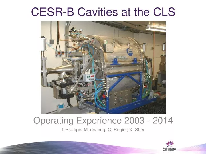
CESR-B Cavities at the CLS Operating Experience 2003 - 2014 J. Stampe, M. deJong, C. Regier, X. Shen
CLS Storage Ring and RF System • 2.9 GeV electron storage ring / Synchrotron • 170.88 m circumference • Eloss per turn: ~ 1.1 MeV with all insertion devices operating • ~10 mm bunch length • Thales TH2161B Klystron amplifier • 310 KW CW RF Power at 500 MHz • Accel built CESR-B RF Cavities • Total RF Voltage: 2.2 to 2.4 MV • Maximum Current: ~250 mA
Cavity 1 Operating Experience Cavity #1 delivered in May 2003, commissioned August 2003 Q0 = 8x10⁸ at the designed 8 MV/m field External Q was 192,000 Static heat losses in the cavity and transfer system ~ 35 W Removed late 2004 for commissioning Cavity #2 Reinstalled November 2005 Cavity #1 was stored under dry nitrogen for one year Cavity #1 operating at 2.2 MV for storage ring operation within 4 hours of cool-down Removed after UHV leak January 2013 Currently under repair by Research Instruments • Typical Operation: • 2.2 to 2.4 MV with 250 mA beam current • 229 kW RF power input with all insertion devices on • ~ 40 to 50 W power dissipation into LHe immediately after conditioning • Climbs to ~ 90 to 100 W after two weeks due to cavity contamination • Regular pulse conditioning and partial warm-ups enhance performance
Issues with Cavity 1 • Arc Detectors: false arc trips, decreasing sensitivity - resolved with radiation hard High OH fibre under 20 cm lead shielding and coincidence detection from dual detectors • Marginal ability to support 250 mA beam current with gradually increasing I.D. loads - Due to limited He transfer line capacity and high heat dissipation at required RF voltage when cavity “dirty” • High phase sensitivity to helium pressure variations • Some intermittent “CLTS” cryogenic temperature sensors - Redundant sensors to be added in critical locations • Hex gas heater failure • UHV leak from helium vessel
<> Helium Pressure / RF Phase Fluctuationsbefore/after cryo valve controller change Siemens Valve controllers Samson Valve controllers
Cryostat He vessel PRV“Normally Open” electric/air PRV could allow contamination of cryo system if air supply or 24V power to PRV drops out - 1.33 Bar mechanical PRV added after 1.45 Bar electric PRV. - Burst disk provides fast redundant protection. PRVs tend to leak after activation due to ice in PRV, heating required to thaw- Dual PRV branches installed. A single valve can select second branch after PRV activation to allow first branch to thaw.
Hex Gas Heater Failure • Lightning strike on power line • Control loop power supply failure caused prolonged full power heater operation with no cryogenic flow • Hex heater damaged • Cryostat warmup and insulation vacuum venting required to replace components
A little too warm… Heater cut-outs added
Cavity 1 UHV Vacuum LeakJanuary 2013 Cavity Pressure and Residual Gas Analysis
Cavity 1 removed for repairLeak found from He vessel to UHV at RF pickup
Cavity 2 Commissioning and Initial Operation • Cavity #2 delivered August 2004, and commissioned January 2005 • Q0= 1.1x10⁹ at 6.6 MV/m field (2.0 MV) • External Q = 222,000 • Same static heat losses as Cavity #1 • Initial Operation: • Less difficulty balancing LHe and cold return gas flows – discovered a problem with HEX gas controller on Cavity #1 • Operation at 8 MV/m demonstrated after some months • Typical storage ring beam current 150 mA in 2005 • Intermittent quenching observed • Encountered a very small leak into the insulation vacuum. • Countered by operating a turbo continuously on insulation vacuum • Cavity 2 removed October 2005, Cavity 1 reinstalled • Cavity 2 reinstalled January 2013 after Cavity 1 failure
Issues with Cavity 2 • Insulation vacuum leak - Initially small, thought to be from helium connection - Much larger “Boot Box” leak found later when cavity 2 reinstalled after cavity 1 UHV failure • Leak from N2 waveguide volume found - Area between kapton window and RF window, • Currently operating without N2 in waveguide • Cavity UHV issues • Intermittent quenching as vacuum deteriorates, could not run reliably at high RF voltage
Cavity 2 Insulation Vacuum Leak O-ring seal around perimeter “Boot Box” Cavity lifted and frame reversed to allow box removal
Boot Box O-ring Leak Cavity 1 Cavity 2
Cavity 2 UHV Issues • Outgassing as function of beam related heating • Slow improvement with partial warm-ups • Full warm-ups while pumping during maintenance outages • Will likely require significant time to reach vacuum quality of Cavity 1 • Plan to also install added NEG pumping, TSPs etc. around cavity as cavity “cryo-pumps” storage ring
Situation Early 2013: RF Power Delivery for 250 mA Beam and ID Load Insufficient at Available RF Cavity Voltage • Cavity 2 vacuum still gradually conditioning. Partial warm-ups (50 K) and cavity UHV pump-outs required to evacuate H2, N2. etc. • Cavity intolerant of high RF voltage: Cavity quenching at gradually decreasing voltage threshold between partial warm-ups • Increased Operational ID beam loads: - BMIT SCW field increase from 2.0 to 4.1 T; 10 Kw additional load, already problematic with Cavity 1 at higher RF voltage - BioXASID on line;12 Kw additional load • Limited combination of beam current and ID loads allowable at voltage allowable to reduce quench frequency • Current load including dipoles 247 Kw • Projected total load with future IDs 298 Kw • Qext needed to be lowered to increase available beam power at lower cavity voltage
Cavity 2 Qext Adjustment Cavity 2 Qext = 222,000 Cavity 1 Qext = 192,000 Waveguide tuners implemented at other facilities to lower Qext Simple approach: Add “Lumped Constant” in waveguide to change cavity Qext H plane aperture reduction chosen 3 potential locations close to cavity RF waveguide input
Waveguide Iris Measurements Sliding H Aperture Adjustments Qext and Freq. Pull Measurements 3 Locations Tested
Waveguide aperture reduced in magnetic plane Qext change and frequency pull noted Qext Reduction Test
Ready for high power test… Irises Machined Selected and Installed
Cavity 2 Performance Mid 2013 • Cavity 2 Qext was dropped from 222,000 to 170,000 during April 2013 Outage • Frequency pull approx. 30 kHz • Partial cavity warm-ups still required every 2 weeks due to cavity outgassing / poor vacuum • More reliable cavity performance with high beam loads at lower cavity voltage / less quenching but still unable to maintain full ID loads for 2 week period at 250 mA without cavity quenches at required Cavity V • Beam current limited to 230 mA to allow all IDs to operate at max. loads without cavity quenches
Qext reduced to 150,000 in October 2013 Outage • 140 mm total reduction of W/G H aperture • Additional frequency pull ~ 12 kHz Current Cavity 2 Operation • All present IDs can be run reliably at max load with 250 mA: ~ 240 kW beam power, 260 kW Klystron PF, Cavity V = 2.05 MV • Low power dissipation into LHe, ~ 40-50 W • No quenches, partial warm-ups continue • High power test done with all present IDs at max load, 300 mA, 300 kW PF, ~ 280 kW beam power (~ 40 kW reserve beam power at 250 mA) • Higher beam power will require 2 installed cavities and more RF power
Current CLS LHe and RF System LayoutSingle Amplifier and Cavity, Long Cryo Transfer Line
Future Plans: Proposed Layout2 Installed Cavities, 2nd Amplifier and Cryo Move / Upgrade for 500 mA- 2 Cavities initially to be fed from 1 Amplifier via high power splitter--
Cryostat Partial Warm-up Procedure (50K) • Cryoplant in part load – start turbo pumps on cavity UHV and insulation vac • Leave GHe return valve (cryostat pressure control valve) in auto mode • Close LHe supply valve (cryostat level control valve) – manual mode • Bring cryostat heater to 120W output to boil off LHe and warm up cavity • When cryostat is empty cavity vacuum pressure will start to increase • Turn off cavity ion pumps • When cavity pressure is 1 order of magnitude above turbo pressure (~30min) Open valves to turbos • After cavity temp reaches 50K follow cool-down procedure to re-cool cavity • Refill cryostat • Takes about 12 hours to complete
Thales Electron Devices TH20536C Window Specification(T.E.D. drawing)