Download
1 / 16
160 likes | 332 Views
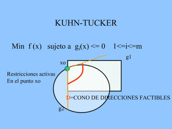
Optical Buffers for High-Capacity Routers. Rod Tucker ARC Special Research Centre for Ultra-Broadband Information Networks (CUBIN)

E N D
Optical Buffers for High-Capacity Routers Rod Tucker ARC Special Research Centre for Ultra-Broadband Information Networks (CUBIN) Department of Electrical and Electronic Engineering University of Melbourne, Australia
Optical Buffers Control Variable Delay Dispersion Compensator Waveguide Delay Line Amplifier Delay Recirculating Loop Cross Point Staggered Delay Line Delay Cross Point Cross Point
Summary Optical Buffers Electronic Buffers • 20-nm CMOS (~ 2020) • Fiber, Slow Light • Fundamental limitations • Delay-Bitrate Product • Storage Density (Bit Size) • Power/Energy • Dispersion • Waveguide attenuation International Technology Roadmap for Semiconductors http://public.itrs.net/ More conservative projections than for Optics Loss Happens! • Compare key parameters: • Power dissipation • Physical size
Total fibre length ~ 100 Gm Distance from the Sun to Earth 100 Tb/s Router – Buffer Size 2,500 ports at 40 Gb/s, 250 ms buffering per port Electronic Router CMOS Buffers Total buffer capacity 25 Tb ~ 103 RAM chips @ 2.5 GB/chip Optical Router Fibre Delay Line Buffers . Sun Earth
. Packet Switching with Reduced Buffering Enachescu et al., ACM/SIGCOMM July 2005: Buffer size can be reduced Optical Router Fibre Delay Line Buffers Total fibre length = 500 Mm (200 km/port) Distance from Earth to the Moon 1 ms buffering per port (100 Gb total) Buffering with fiber delay lines is challenging
Large Slow-Light to the Rescue? Photonic Crystal Electromagnetically-Induced Transparency in Semiconductor Group Velocity Attenuation Hilbert Transform Effective Refractive Index n Refractive Index n Optical frequency C.J Chang-Hasnain et al., Proc IEEE, 9, 2003 Y. Xu et al., QELS, 2000
Car Analogy 20 100 km/h Speed Limit 20 km/h Speed Limit Real World Slow Light World Reduced Group Velocity Constant Bitrate Lbit
Some Numbers 100-Tb/s Optical Router 1 ms buffering per port (100 Gb total) Fiber 200 km/port, 0.5 Gm total Storage Density: 1 bit / 5 mm Ideal Slow Light Waveguide 40 m/port, 100 km total Storage Density: ~1 bit / mm Slow Light Waveguide Slow-down factor = 5x10² 400 m/port, 1 Mm total Storage Density: 1 bit / 10 mm . Wavelength
80 nm 1 cell eDRAM cell area 80 nm x 80 nm 150 Tbit/m2 Capacity 700 cm2 100 Gbit 0.7 cm2 Area 17 m2 2.5 Tbit 170 cm2 Size Matters Non-Ideal Slow Light Waveguide Ideal Slow Light Waveguide CMOS (2018) ~5l l 100l 1 bit Minimum bit area ~ 500l2(l = ~1 mm) Minimum bit area ~ 5l2(l = ~1 mm) Storage Density 150 Gbit/m2 1.5 Gbit/m2 per wavelength 70 m2 1,700 m2
Size required to store 200 IP packets Slow Light Waveguide (200 m) CMOS 5l 100l 1 bit 4 cm 0.02 mm2 Fiber (10 km) 10 cm 4 cm 10 cm 5 cm
Loss Fibre: ~0.2 dB/km In Out 15 km for 3-dB loss Photonic Crystal WG: 0.1 dB/cm Out In 6 mm for 3-dB loss 200 m (200 packets) 33,000 dB 20 m (20 packets) 3,000 dB
Putting it All Together: Delay Line Buffer Stage 1 Stage m Power Power Signal Signal b g b g Psat L Noise Two key limitations: Slow light waveguide • Output SNR • Amplifier Saturation Power Dispersion compensation Waveguide loss compensation
Fiber + crosspoints Energy per Bit in Slow Light Buffers 100 M Contention Resolution 1 M Packet Synchronization 0.05 dB/cm 10 k Slow Light 10-11 Capacity, (b) 100 10-12 0.5 dB/cm 10-13 Energy per bit (J) 1 CMOS eDRAM* 10-14 All delay line buffers 10-15 10-16 100 mW 10 mW 10 mW 1 mW 100 mW 1 mW Saturation power, Psat *International Technology Roadmap for Semiconductors: Projections for 2018
Optical and Electronic Buffers Optical Buffer Optical Cross Connect Optical Inputs O/E CMOS Buffer E/O 5 mW 7 mW 7 mW 10-4 Buffer 10-2 O/E E/O 10-2 20 mW CMOS 20 mW 10-2 20 mW 2x10⁻² 20 mW 10-2 Total Viable buffer solutions
Conclusions • Slow light and fiber delay lines struggle to compete with CMOS • Power dissipation and dispersion are key issues • Research challenges for optical buffering: • Waveguide losses << 0.1 dB/cm • Integration of gain and dispersion compensation • Crosspoint power dissipation and footprint
Dispersion Limits in Slow Light Buffers Maximum (Slow-down factor = 1) and fiber 40 Gb/s 10 mm PC EIT 1 mm 0.5 dB/cm 0.05 dB/cm Stored bit length, Lbit 100 mm CRW Psat = 100 mW 10 mm 1 mm Minimum (Ideal) 1 10 0.1 10 k 100 1 k 100 k Number of stored bits, Nbit (b)