Download
1 / 22
740 likes | 1.82k Views
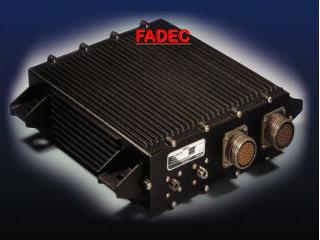
FADEC. Full Authority Digital Engine Control. FADEC Overview. Full Authority Digital Engine Control System continuously monitors and controls ignition timing, fuel injection timing, and fuel-to-air ratio mixture

E N D
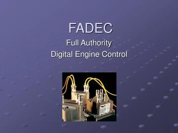
FADEC Full Authority Digital Engine Control
FADEC Overview • Full Authority Digital Engine Control • System continuously monitors and controls ignition timing, fuel injection timing, and fuel-to-air ratio mixture • Therefore, a FADEC equipped engine does not require magnetos and eliminates the need for manual fuel/air mixture control.
Basic components of FADEC • Two Electronic Control Units (ECUs) • Health Status Annunciator (HSA) • FADEC Sensor set • (1) Speed Sensor Assembly (SSA) • (4) Cylinder Head Temperature (CHT) • (4) Exhaust Gas Temperature (EGT) • (2) Manifold Air Pressure (MAP) • (2) Manifold Air Temperature (MAT) • (2) Fuel Pressure Sensors • (1) Throttle Position Switch (WOT)
Low Voltage HarnessFigures 3-2 and 3-1 in FADEC manual • Connects all essential components of FADEC • Fuel Injector Coils and all sensors (except SSA, Fuel Pressure, Manifold Pressure) are hardwired to the low voltage harness • All information from sensors will flow to the Electronic Control Units for data processing and analysis
Electronic Control Unit (ECU)3-7 to 3-9 in FADEC manual • “Brain” of the Engine Control System • ECU divided into an upper and lower portion • Lower portion contains the Electronic Circuit Board that processes all data • Upper portion contains the ignition coils for the spark plugs (each ECU has (4) coils)
ECU cont’d • The electronic circuit board (lower portion) of each ECU contains (2) independent microprocessor controllers which serve as control channels • (1) control channel is assigned to operate a single engine cylinder (thus one ECU per pair of cylinders) • ECU #1 controls opposing cylinders 1& 2…ECU #2 controls opposing cylinders 3 & 4
ECU cont’d • Control channel will receive the sensor inputs and monitor any changes • Control channel will use these inputs to precisely trim the fuel to air ratio going into each cylinder • Therefore, the control channels allow each cylinder to be individually leaned or enriched
ECU cont’d • If one control channel fails within an ECU the other control channel can operate it’s assigned cylinder as well as the opposing cylinder as backup control for fuel injection and ignition timing • All critical sensors are redundant with one sensor from each type connected to a control channel in different ECUs • Synthetic software default values are also used should both sensors of a redundant pair fail…therefore, FADEC will always have a value to work off of so it can inject an average amount of fuel to the cylinder
HSA cont’d • Consists of (5) lights on panel and WOT • HSA provides information regarding the status of the FADEC system • We have the 2-light system display referenced in the manual plus additional indicators as seen on the HSA • HSA will not give you a warning or caution light for OIL temp/pressure or ALT FAIL
HSA lights • FADEC WARN: Engine Failure may be imminent, more than (1) cylinder is affected…land ASAP • FADEC CAUTION: 99.99% of installed components are working. No immediate action is req’d. Most common example is a bad EGT sensor…all sensors are redundant • ANYTIME YOU GET A WARNING OR CAUTION REFER TO VM1000…this is a window into what FADEC sees
HSA lights cont’d • PPWR FAIL: Primary Battery is not being charged, will be accompanied by EBAT FAIL…you will start draining both batteries and have at least 60 minutes to land. Your secondary battery will only power FADEC, AI, and Turn Coordinator • EBAT FAIL: Backup Battery not being charged, everything can run from Primary Power Source/Battery
HSA Lights cont’d • FUEL PUMP: illuminates when Fuel Boost Pump Mode Switch is in ON or OFF. If this light is illuminated it means that you are manually controlling the fuel pump or that the fuel pressure is out of the 20-40 psi range. Illuminates for electric driven fuel pump as well as engine driven pump • WOT: below HSA panel. Illuminates when Throttle Position Switch (TPS) is contacted (full throttle), signal sent to ECU that max power is req’d which causes FADEC to set fuel to air ratio for Best Power
FADEC Ignition System • Consists of high voltage harness and spark plugs (2 plugs per cylinder) • Employs a waste spark ignition system- plugs fire once on compression and once on exhaust... this keeps plugs clean • ECU#1 fires top and bottom spark plugs for cylinders 1 & 2 • ECU#2 fires top and bottom spark plugs for cylinders 3 & 4
Power Supplies • Primary Power Source (PPS)- • 14v 60amp alternator and 12v 25Ah Lead Acid type battery (located aft baggage compartment) • Secondary Power Source (SPS)- • 12v 7Ah Lead Acid type battery • PPS and SPS have separate set of breakers and the power supply circuits are separated • Battery condition monitor will illuminate HSA with PPWR FAIL or EBAT FAIL to alert pilot of possible power supply loss
Power Supplies cont’d • FADEC operates off of primary power source with alternator indefinitely • Alternator fails- FADEC will use primary battery until 12v then will cycle between using PPS and SPS every volt (FADEC always looking for best power source) until batteries are drained • FADEC can operate on SPS (aka backup or emergency battery) for at least 1 hour • SPS is only to supply power to FADEC (AI and TC will also work) and can not be used for starting
FADEC System Redundancy • Power Supplies (PPS and SPS) • If a control channel (CC) has a fault, the other CC within the same ECU is capable of operating its assigned cylinder as well as the other cylinder experiencing the fault • All sensors are redundant with one sensor from each pair connected to channels in different ECUs. Synthetic software defaults are used in case of sensor failure
REVIEW • FADEC utilize a set of redundant sensors linked to the respective ECU • ECU then uses data to analyze and control the ignition timing, fuel injection timing and fuel to air ratio for each cylinder • FADEC is powered by 3 sources: alternator, primary battery, emergency battery…FADEC needs only 1 power source to operate • Reduces a pilot’s “busy work” • 15% more fuel efficiency than correct and accurate conventional mixture control