Download
1 / 25
250 likes | 359 Views
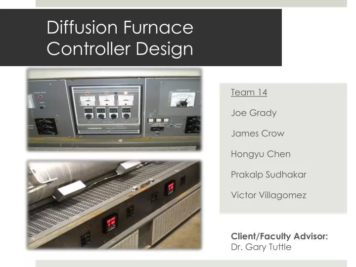
Diffusion Furnace Controller Design. Team 14 Joe Grady James Crow Hongyu Chen Prakalp Sudhakar Victor Villagomez Client/Faculty Advisor: Dr. Gary Tuttle. Project Goals.

E N D
Diffusion Furnace Controller Design Team 14 Joe Grady James Crow Hongyu Chen Prakalp Sudhakar Victor Villagomez Client/Faculty Advisor: Dr. Gary Tuttle
Project Goals The objective of the senior design project is to design a new set of temperature controllers to use on a set of diffusion furnaces located at the Microelectronics Research Center. The project goals include: Updating analog controlled furnace to a digitally controlled furnace. Implementation of a new digital temperature controller integrated into the current microelectronics oven Providing a software interface so that temperature of the furnaces can be controlled and monitored remotely.
Controller must • have a temperature tolerance within +/- 5 degree Celsius • be digital and programmable • have communication capability • be able to control temperatures independently of each section • Software must be able • to monitor and control the parameters of the temperature controller • to support multiple students • to be accessed online via web browser Functional Requirements
The new controllers need to be placed where the old ones were so they need to able to fit within a certain space • Connectors must be compatible with the new controller • All the schematics and layout designs need to be of industry standards for future reference. • Graphical interface of the software must be user-friendly Non-functional Requirements
The amount of inputs on the CN616 controller will not allow us to use all of thermocouples used in the old set-up; in the new setup, there is no differential thermocouple pairs between zones.Each zone is now controlled by a single SCR pair and a thermocouple • If the controller has been setup remotely, there is no way to stop someone from adjusting the controller manually • There is no way to prevent a user from opening the oven door before process is complete Risks and Mitigations
Software System Design Overview Browser Webserver Sends parameters to webserver Sends commands to controller Sets up furnace Responds to controller Sends feedback to webserver Updates data on browser Furnace Controller
Website UI Flow For user to setup the furnace and checking the status.
Hardware Testing Compatibility testing SCR with our Opto-isolator Circuit
Software Implementation Technologies • Web Browser Module • PHP • CGI (Common Gateway Interface • Web Server Module • Apache • Controller Comm Module • CGI in C • UNIX POSIX serial port API
Software Implementation RS-232 Interface • USB to serial adapter for Mac Mini • Read Input data CGI • Serial Port • Open • Read • Write
Software Testing • Blackbox Testing • CubicTestTools • A graphical Eclipse plug-in • For writing Selenium and Watir tests.
Single Oven System Test • Connected our opto-isolator circuit to the gates of the SCR • Used a power supply to turn on each zone individually • Used a multi-meter to verify correct voltages on each zone • Replaced the power supply with the controller • Made the appropriate thermocouple and control connections • Manually set the controller to verify the voltages for each zone
Set the controllers to PID control to improve overshoot, rise time and settling time • Website compatible with more commands • Website can be more user friendly by • Temperature data plot • Data saving Project Future
Able to meet customer requirements • Hardware met specifications • Software met specifications Conclusions