Download
1 / 32
340 likes | 491 Views
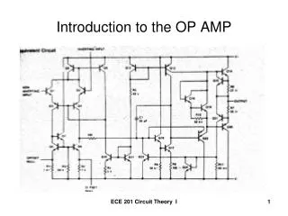
Introduction to Op Amp Circuits. ELEC 121. Basic Op-Amp. The op-amp is a differential amplifier with a very high open loop gain 25k ≤ A VOL ≤ 500k (much higher for FET inputs) high input impedance 500k ≤ Z IN ≤ 10M low output impedance 25 ≤ R O ≤ 100 .

E N D
Introduction to Op Amp Circuits ELEC 121
Basic Op-Amp The op-amp is a differential amplifier with a very high open loop gain 25k ≤ AVOL ≤ 500k(much higher for FET inputs) high input impedance 500k ≤ ZIN≤ 10M low output impedance 25≤RO≤100 ELEC 121 Op Amps
Op-Amp Equivalent Circuit ELEC 121 Op Amps
Op-Amp Specifications – DC Offset Parameters • Even though the input voltage is 0, there will be an output. This is called offset. The following can cause this offset: • Input Offset Voltage • Output Offset Voltage due to Input Offset Current • Total Offset Voltage Due to Input Offset Voltage and Input Offset Current • Input Bias Current • See lm301.pdf or mc1741c.pdf for sample specification sheets ELEC 121 Op Amps
General Op-Amp Specifications VIO • Input Offset Voltage VIO • The voltage that must be applied to the input terminals of an op amp to null the output voltage • Typical value is 2mV with a max of 6mV • When operated open loop, must be nulled or device may saturate ELEC 121 Op Amps
General Op-Amp Specifications IIO • Input Offset Current • The algebraic difference between the two input currents • These are base currents and are usually nulled • Typical value IIO 20 nA with a max of 200nA ELEC 121 Op Amps
Technique to Null VO • Short Input terminals to ground • Connect potentiometer between compensation pins with wiper to VEE • Potentiometer is usually a 10 turn device • Connect meter to output and adjust potentiometer for VO = 0 ELEC 121 Op Amps
General Op-Amp Specifications CMRR • Common Mode Rejection Ratio • The ratio of the differential voltage gain (AD) to the common mode gain (ACM) • ACM is the ratio between the differential input voltage (VINCM) applied common mode, and the common mode output voltage (VOCM) • it can exceed minimum is 70db with a typical value of 90 db • in properly designed circuit, it may exceed 110db ELEC 121 Op Amps
General Op-Amp Specifications • Input Bias Current • The average of the currents that flow into the inverting and noninverting terminals • Typical values rage from 7nA to 80 nA • Differential Input Resistance • Also know as the input resistance • Resistance seen looking into the input terminals of the device • Runs from a low of 2M for an LM741 to a high of 1012 for FET input devices • Output resistance • Resistance between the output terminal ad ground • Typical values are 75 or less • Input Capacitance • The equivalent capacitance measured at either the inverting or noninverting terminal with the other terminal connected to ground • May not be on all spec sheets • Typical value for LM741 is 1.4pF ELEC 121 Op Amps
General Op-Amp Specifications • Power Supply Range • May be differential or single ended • Max is ± 22V • Output Voltage Swing • Range of output voltage • Depends on power supply voltage used (typically about 85% to 90%) • Usually about ±13.5V for a power supply voltage of ±15V • Slew Rate • The maximum rate of change in the output voltage in response to an input change • Depends greatly on device, higher is better (output resonds faster to input changes) • For LM741 it is .5V/s while for the LM318 it is 70V /s • Gain Bandwidth Product • The bandwidth of the device when the open loop voltage gain is 1 ELEC 121 Op Amps
Op Amp Equivalent Circuit ELEC 121 Op Amps
Op-Amp Gain • Op-Amps have a very high gain. They can be connected open- or closed loop. • Open-loop (AVOL) refers to a configuration where there is no feedback from output back to the input • AVOL may exceed 10,000 • Closed-loop (AVCL) configuration reduces the gain In order to control the gain of an op-amp it must have negative feedback • Negative feedback will reduce the gain and improve many characteristics of the op-amp ELEC 121 Op Amps
Typical Op Amp Frequency Response ELEC 121 Op Amps
Change in AV with Feedback ELEC 121 Op Amps
Virtual Ground Since ZIN is very high, we assume no current can flow into any lead of the op amp When the non-inverting input pin is at ground, the inverting input pin is at 0V The equivalent circuit. ELEC 121 Op Amps
Practical Op-Amp Circuits • Typical Op-amp circuit configurations include the: • Unity Gain Buffer (Voltage Follower) • Inverting Amplifier • Noninverting Amplifier • Summing Amplifier • Integrator • Differentiator • Note: the integrator and differentiator are considered active filters ELEC 121 Op Amps
Unity Gain Buffer (Follower) ELEC 121 Op Amps
Inverting Op Amp The input is applied to the inverting (-) input the non-inverting input (+) is grounded RF is the feedback resistor, and is connected from the output to the inverting input This is called negative feedback ELEC 121 Op Amps
Inverting Op Amp We assume that no current enters the inverting terminal II- < 100nA VD 0V ELEC 121 Op Amps
Inverting Op-AmpGain Closed Loop Gain is controlled by the external resistors: RF and R1 For Unity Gain: AV is -1 and RF = R1 The minus sign denotes a 180 degree phase shift between input and output ELEC 121 Op Amps
Inverting Op Amp Compensated for Ibias R is used to compensate for difference in IBIAS+ and IBIAS- ELEC 121 Op Amps
Inverting Op-Amp A This configuration achieves high gain with a smaller range of resistor values than the basic inverter V- V+ ELEC 121 Op Amps
Inverting Amplifier with High Zin Use a Unity Gain Buffer to obtain a very high input resistance with an inverting amplifier ELEC 121 Op Amps
Inverting Amplifier for Low RL Use a Unity Gain Buffer to obtain a very high input resistance to drive a low impedance load ELEC 121 Op Amps
Noninverting Amplifier V- = V+ = vi ELEC 121 Op Amps
Noninverting Op Amp Compensated for IBIAS Rbias is used to compensate for difference in IBIAS+ and IBIAS- ELEC 121 Op Amps
Differential (Difference) Amplifier A V1 V2 A ELEC 121 Op Amps
Differential Amplifier Output ELEC 121 Op Amps
Instrumentation Amplifier Buffered Input R1 = R2, RF1 = RF2 ELEC 121 Op Amps
Instrumentation Amplifier R1 = R2, RF1 = RF2 ELEC 121 Op Amps
Inverting Summing Amplifier • By applying KCL to the multiple inputs, we can consider the contribution of each source individually • IF + I- = I1 + I2 + I3 • but I- 0 • IF = I1 + I2 + I3 VO = -IF RF ELEC 121 Op Amps
Non-inverting Summing Amplifier Perform a source transformation for each input Sum the current sources and find RTH for the resistances VIN+ = IT RTH ELEC 121 Op Amps