Download
1 / 26
280 likes | 442 Views
CS 203A Advanced Computer Architecture. Lecture 2 Performance, Instruction Set Principles, Pipeline Hazards. Instructor: L.N. Bhuyan. RISC Vs CISC. CISC (complex instruction set computer) VAX, Intel X86, IBM 360/370, etc. RISC (reduced instruction set computer)

E N D
CS 203AAdvanced Computer Architecture Lecture 2Performance,Instruction Set Principles, Pipeline Hazards Instructor: L.N. Bhuyan Lec. 3
RISC Vs CISC • CISC (complex instruction set computer) • VAX, Intel X86, IBM 360/370, etc. • RISC (reduced instruction set computer) • MIPS, DEC Alpha, SUN Sparc, IBM 801 Lec. 3
RISC vs. CISC • Characteristics of ISAs Lec. 3
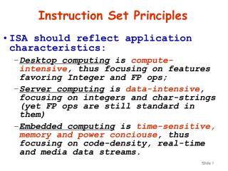
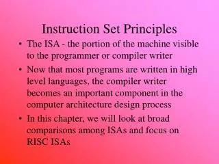
RISC vs. CISC Instruction Set Design • The historical background: • In first 25 years (1945-70) performance came from both technology and design. • Design constraints: • small and slow memories: compact programs are fast. • small no. of registers: memory operands. • attempts to bridge the semantic gap: model high level language features in instructions. • no need for portability: same vendor application, OS and hardware. • backward compatibility: every new ISA must carry the good and bad of all past ones. • Result: powerful and complex instructions that are rarely used. • IC technology and microprocessors in 1970s: lower costs, low power consumption, higher clock rates, cheaper and larger memories. Lec. 3
Top 10 80x86 Instructions Lec. 3
RISC vs. CISC Instruction Set Design • Emergence of RISC • Very large scale integration (processor on a chip): silicon real-estate at a premium. Micro-store occupies about 70% of chip area: replace micro-store with registers ==> load/store ISA. • Increased difference between CPU and memory speeds. • Complex instructions were not used by new compilers. • Software changes: • reduced reliance on assembly programming, new ISA can be introduced. • standardized vendor independent OS (Unix) became very popular in some market segments (academia and research) – need for portability • Early RISC projects: IBM 801 (America), Berkeley SPUR, RISC I and RISC II and Stanford MIPS. Lec. 3
31 26 21 16 11 6 0 op rs rt rd shamt funct 6 bits 5 bits 5 bits 5 bits 5 bits 6 bits 31 26 21 16 0 immediate op rs rt 6 bits 5 bits 5 bits 16 bits 31 26 0 op target address 6 bits 26 bits The MIPS Instruction Formats • All MIPS instructions are 32 bits long. The three instruction formats: • R-type • I-type • J-type • The different fields are: • op: operation of the instruction • rs, rt, rd: the source and destination register specifiers • shamt: shift amount • funct: selects the variant of the operation in the “op” field • address / immediate: address offset or immediate value • target address: target address of the jump instruction Lec. 3
MIPS Instruction Layout Lec. 3
register register MIPS Addressing Modes/Instruction Formats • All instructions 32 bits wide Register (direct) op rs rt rd Immediate immed op rs rt Displacement immed op rs rt Memory + PC-relative immed op rs rt Memory + PC Lec. 3
Summary: Instruction Set Design (MIPS) • Use general purpose registers with a load-store architecture: YES • Provide at least 16 general purpose registers plus separate floating-point registers: 31 GPR & 32 FPR • Support basic addressing modes: displacement (with an address offset size of 12 to 16 bits), immediate (size 8 to 16 bits), and register deferred; : YES: 16 bits for immediate, displacement (disp=0 => register deferred) • All addressing modes apply to all data transfer instructions : YES • Use fixed instruction encoding if interested in performance and use variable instruction encoding if interested in code size : Fixed • Support these data sizes and types: 8-bit, 16-bit, 32-bit integers and 32-bit and 64-bit IEEE 754 floating point numbers: YES • Support these simple instructions, since they will dominate the number of instructions executed: load, store, add, subtract, move register-register, and, shift, compare equal, compare not equal, branch (with a PC-relative address at least 8-bits long), jump, call, and return: YES • Aim for a minimalist instruction set: YES Lec. 3
Review: 5-stage Execution • 5 canonical stage “RISC” load-store architecture • Instruction fetch (IF): • get instruction from memory/cache • Instruction decode, Register read (ID): • translate opcode into control signals and read regs • Execute (EX): • perform ALU operation, load/store address, branch outcomes • Memory (MEM): • access memory if load/store, everyone else idle • Writeback/retire (WB): • write results to register file Lec. 3
PC Registers ALU Stage 1 Stage 2 Stage 3 Stage 4 Review: Single-cycle Datapath for MIPS Stage 5 Instruction Memory (Imem) Data Memory (Dmem)
6 IF 11 1 IF IF IF IF IF 2 ID 7 ID ID ID ID ID 12 EX EX EX EX 3 EX 13 8 EX MEM MEM 14 MEM MEM 9 MEM MEM 4 WB 15 5 WB WB WB WB WB 10 Solution • Overlap execution of instructions • Start instruction on every cycle, e.g. the new instruction can be fetched while the previous one is decoded – pipeline. Each cycle performing a specific task; number of stages is called pipeline depth (5 here) Non-pipelined time Pipelined Lec. 3
Pipelined Datapath (with Pipeline Regs) Fetch Decode Execute Memory Write Back 0 M u x 1 IF/ID EX/MEM ID/EX MEM/WB A d d A d d 4 A d d r e s u l t S h i f t l e f t 2 R e a d n o r e g i s t e r 1 i A d d r e s s P C t R e a d c u d a t a 1 r R e a d t s Z e r o n r e g i s t e r 2 I A L U R e a d A L U 0 R e a d W r i t e A d d r e s s d a t a 2 r e s u l t 1 d a t a r e g i s t e r M M Imem Regs u u W r i t e x x d a t a 1 0 W r i t e d a t a 1 6 3 2 S i g n e x t e n d Dmem 5 69 bits 133 bits 64 bits 102 bits
RegDstALUopALUSrc Pipelined Control Review • Start with single-cycle controller • Group control lines by pipeline stage needed • Extend pipeline registers with control bits W B I n s t r u c t i o n Mem W B C o n t r o l E X W B Mem MemToRegRegWrite Branch MemReadMemWrite I F / I D I D / E X E X / M E M M E M / W B Lec. 3
+ + A L U Pipeline Progress – Instn moves with all control signals, addresses, data items => different register lengths at different stages M U X 1 target PC+1 PC+1 0 R0 eq? R1 regA ALU result R2 Register file regB valA M U X PC Inst mem Data memory instruction R3 ALU result mdata R4 valB R5 R6 M U X data R7 offset dest valB Bits 11-15 dest dest dest Bits 16-20 M U X IF/ ID ID/ EX EX/ Mem Mem/ WB Lec. 3
A pipeline with multi-cycle FP operations: Arithmetic Pipeline: Ex. MIPS R4000 Lec. 3
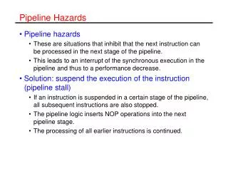
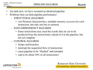
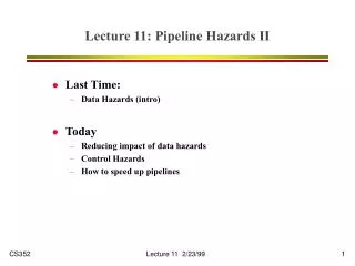
Pipeline Hazards • Hazards are caused by conflicts between instructions. Will lead to incorrect behavior if not fixed. • Three types: • Structural: two instructions use same h/w in the same cycle – resource conflicts (e.g. one memory port, unpipelined divider etc). • Data: two instructions use same data storage (register/memory) – dependent instructions. • Control: one instruction affects which instruction is next – PC modifying instruction, changes control flow of program. Lec. 3
Handling Hazards • Force stalls or bubbles in the pipeline. • Stop some younger instructions in the stage when hazard happen • Make younger instr. Wait for older ones to complete • Implementation: de-assert write-enable signals to pipeline registers • Flush pipeline • Blow instructions out of the pipeline • Refetch new instructions later – solving control hazards • Implementation: assert clear signals on pipeline registers Lec. 3
Dealing with Structural Hazards • Stall + simple, low cost in h/w • Decrease IPC • Replicate the resource + good for performance • Increase h/w and area • Used for cheap resources • Pipeline the resource + good for performance • Complexity, e.g. RAM • Useful for multicycle resources Lec. 3
M ALU M M Reg Reg ALU M M Reg Reg ALU ALU M M Reg Reg ALU Single Memory is a Structural Hazard Time (clock cycles) I n s t r. O r d e r M Reg Reg Load Instr 1 Instr 2 M M Reg Reg Instr 3 Instr 4 • Can’t read same memory twice in same clock cycle Lec. 3
Speed Up Equation for Pipelining CPIpipelined = Ideal CPI + Pipeline stall clock cycles per instn Ideal CPI x Pipeline depth Clock Cycleunpipelined Speedup = -------------------------- X -------- Ideal CPI + Pipeline stall CPI Clock Cyclepipelined Pipeline depth Clock Cycleunpipelined Speedup = ------------------------ X --------------- 1 + Pipeline stall CPI/Ideal CPI Clock Cyclepipelined Lec. 3
Example: Dual-port vs. Single-port • Machine A: Dual ported memory • Machine B: Single ported memory, but has a 1.05 times faster clock rate • Ideal CPI = 1 for both • Loads are 40% of instructions executed SpeedUpA = Pipeline Depth/(1 + 0) x (clockunpipe/clockpipe) = Pipeline Depth SpeedUpB = Pipeline Depth/(1 + 0.4) x (clockunpipe/(clockunpipe / 1.05) = (Pipeline Depth/1.4) x 1.05 = 0.75 x Pipeline Depth SpeedUpA / SpeedUpB = Pipeline Depth/(0.75 x Pipeline Depth) = 1.33 • Machine A is 1.33 times faster Lec. 3
add R1, R2, R3 sub R2, R4, R1 or R1, R6, R3 add R1, R2, R3 sub R2, R4, R1 or R1, R6, R3 add R1, R2, R3 sub R2, R4, R1 or R1, R6, R3 Data Hazards • Two different instructions use the same storage location • It must appear as if they executed in sequential order write-after-read (WAR) write-after-write (WAW) read-after-write (RAW) True dependence (real) anti dependence (artificial) output dependence (artificial) Where (How) do WAR and WAW hazards occur ? Lec. 3
Control Hazards • Branch problem: • branches are resolved in EX stage 2 cycles penalty on taken branches Ideal CPI =1. Assuming 2 cycles for all branches and 32% branch instructions new CPI = 1 + 0.32*2 = 1.64 • Solutions: • Reduce branch penalty: change the datapath – new adder needed in ID stage. • Fill branch delay slot(s) with a useful instruction. • Fixed branch prediction. • Static branch prediction. • Dynamic branch prediction. Lec. 3