Download
1 / 56
560 likes | 681 Views
The computer system’s I/O architecture is its interface to the outside world. This architecture provides a systematic means of controlling interaction with the outside world and provides the operating system with the information it needs to manage I/O activity effectively

E N D
The computer system’s I/O architecture is its interface to the outside world. • This architecture provides a systematic means of controlling interaction with the outside world and provides the operating system with the information it needs to manage I/O activity effectively • There are three principle I/O techniques: • programmed I/O • interrupt-driven I/O • direct memory access
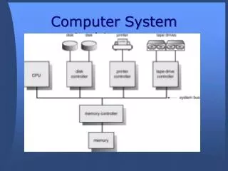
Input/Output Problems • Wide variety of peripherals - Delivering different amounts of data - At different speeds - In different formats • All slower than CPU and RAM • Need I/O modules
Input/Output Module • Interface to CPU and Memory Interface to the processor and memory via the system bus or central switch • Interface to one or more peripherals Interface to one or more peripheral devices by tailored data links
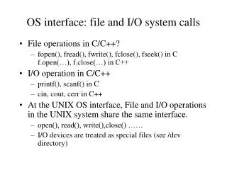
7.1 External devices • Human readable: Suitable for communicating with the computer user (Screen, printer, keyboard) • Machine readable: Suitable for communicating with equipment(Monitoring and control) • Communication: Suitable for communicating with remote devices (Modem, Network Interface Card (NIC) • Fig.(7.2) show Block Diagram of an External Device
The interface to the I/O module is in the form of: • Control signals: determine the function that the device will perform, such as send data to the I/O module (INPUT or READ), accept data from the I/O module (OUTPUT or WRITE), report stat. • Data are in the form of a set of bits to be sent to or received from the I/O module. • Status signals indicate the state of the device, to show whether the device is ready for data transfer.
Examples of interface between the I/O module and the external device are: - Keyboard/Monitor: The most common means of computer/user interaction is a keyboard/monitor arrangement. The user provides input through the keyboard. This input is then transmitted to the computer and may also be displayed on the monitor - Disk Drive: A disk drive contains electronics for exchanging data, control, and status signals with an I/O module plus the electronics for controlling the disk read/write mechanism.
7.2 I/O MODULES • I/O module function: - Control and timing - Processor communication - Device communication - Data buffering - Error detection
I/O module must communicate with the processor and with the external device. Processor communication involves the following: - Command decoding: The I/O module accepts commands from the processor - Data: Data are exchanged between the processor and the I/O module over the data bus. - Status reporting: Because peripherals are so slow, it is important to know the status of the I/O module - Address recognition: Just as each word of memory has an address, so does each I/O device.
the control of the transfer of data from an external device to the processor might involve the following sequence of steps: 1.The processor interrogates the I/O module to check the status of the attached device. 2. The I/O module returns the device status. 3. If the device is operational and ready to transmit, the processor requests the transfer of data, by means of a command to the I/O module. 4. The I/O module obtains a unit of data (e.g., 8 or 16 bits) from the external device. 5. The data are transferred from the I/O module to the processor.
I/O Module Structure • Figure 7.3 provides a general block diagram of an I/O module. The module connects to the rest of the computer through a set of signal lines (e.g., system bus lines). • Data transferred to and from the module are buffered in one or more data registers. • A status register may also function as a control register, to accept detailed control information from the processor. • The logic within the module interacts with the processor via a set of control lines • Each I/O module has a unique address or, if it controls more than one external device
Input output techniques • There are three way of input output techniques: • Programmed • Interrupt driven • Direct Memory Access (DMA)
Programmed I/O • CPU has direct control over I/O - Sensing status - Read/write commands - Transferring data • CPU waits for I/O module to complete operation
Programmed I/O –details • CPU requests I/O operation • I/O module performs operation • I/O module sets status bits • CPU checks status bits periodically • I/O module does not inform CPU directly • I/O module does not interrupt CPU • CPU may wait or come back later
I/O command • CPU issues address - Identifies module (& device if >1 per module) • CPU issues command - Control - telling module what to do -e.g. spin up disk - Test - check status - e.g. power? Error? - Read/Write - Module transfers data via buffer from/to device
Addressing I/O Devices • Under programmed I/O data transfer is very like memory access (CPU viewpoint) • Each device given unique identifier • CPU commands contain identifier (address)
I/O Mapping • Memory mapped I/O - Devices and memory share an address space - I/O looks just like memory read/write - No special commands for I/O - Large selection of memory access commands available • Isolated I/O - Separate address spaces - Need I/O or memory select lines - Special commands for I/O - Limited set
Interrupt Driven I/O • Overcomes CPU waiting • No repeated CPU checking of device • I/O module interrupts when ready
Interrupt Driven I/O basic Operation • CPU issues read command • I/O module gets data from peripheral whilst CPU does other work • I/O module interrupts CPU • CPU requests data • I/O module transfers data
CPU view point • Issue read command • Do other work • Check for interrupt at end of each instruction cycle • If interrupted:- - Save context (registers) - Process interrupt - Fetch data & store • See Operating Systems notes
Identifying Interrupting Module • Different line for each module - PC - Limits number of devices • Software poll - CPU asks each module in turn - Slow • Daisy Chain or Hardware poll • —Interrupt Acknowledge sent down a chain • —Module responsible places vector on bus • —CPU uses vector to identify handler routine • • Bus Master • —Module must claim the bus before it can raise • interrupt • —e.g. PCI & SCSI
When an I/O device completes an I/O operation, the following sequence of hardware events occurs: 1.The device issues an interrupt signal to the processor. 2. The processor finishes execution of the current instruction before responding to the interrupt 3. The processor tests for an interrupt, determines that there is one, and sends an acknowledgment signal to the device that issued the interrupt. The acknowledgment • allows the device to remove its interrupt signal.
4. The processor now needs to prepare to transfer control to the interrupt routine. To begin, it needs to save information needed to resume the current program at the point of interrupt. 5. The processor now loads the program counter with the entry location of the interrupt-handling program that will respond to this interrupt. Depending on the computer architecture and operating system design 6. At this point, the program counter and PSW relating to the interrupted program have been saved on the system stack
7. The interrupt handler next processes the interrupt. This includes an examination of status information relating to the I/O operation or other event that caused an interrupt. 8. When interrupt processing is complete, the saved register values are retrieved from the stack and restored to the registers. 9. The final act is to restore the PSW and program counter values from the stack
Example - PC Bus • 80x86 has one interrupt line • 8086 based systems use one 8259A interrupt controller • 8259A has 8 interrupt lines
Sequence of Events • 8259A accepts interrupts • 8259A determines priority • 8259A signals 8086 (raises INTR line) • CPU Acknowledges • 8259A puts correct vector on data bus • CPU processes interrupt
Intel 82C55AProgrammable Peripheral Interface • The 82C55A is a single-chip, general-purpose I/O module designed for use with the Intel 80386 processor. • Figure 7.9 shows a general block diagram plus the pin assignment for the 40-pin package • The 24 I/O lines are programmable by the 80386 by means of the control register. • The 80386 can set the value of the control register to specify a variety of operating modes and configurations.
Intel 82C55AProgrammable Peripheral Interfa • The 24 lines are divided into three 8-bit groups (A, B, C). Each group can function as an 8-bit I/O port. In addition, group C is subdivided into 4-bit groups (CA and CB), which may be used in conjunction with the A and B I/O ports. Configured in this manner, group C lines carry control and status signals. • The left side of the block diagram is the internal interface to the 80386 bus. It includes an 8-bit bidirectional data bus (D0 through D7), used to transfer data to and from the I/O ports and to transfer control information to the control register.
Intel 82C55AProgrammable Peripheral Interfa • The two address lines specify one of the three I/O ports or the control register. A transfer takes place when the CHIP SELECT line is enabled together with either the READ or WRITE line. The RESET line is used to initialize the module.
Keyboard/Display Interface to 82C55A • Figure 7.10 illustrates its use to control a keyboard/display terminal. The keyboard provides 8 bits of input. Two of these bits, SHIFT and CONTROL, have special meaning to the keyboard-handling program executing in the processor • Two handshaking control lines are provided for use with the keyboard. • The display is also linked by an 8-bit data port. Again, two of the bits have special meanings that are transparent to the 82C55A.
7.5 DIRECT MEMORY ACCESS • Interrupt driven and programmed I/O • require active CPU intervention - Transfer rate is limited - CPU is tied up • DMA Function - Additional Module (hardware) on bus - DMA controller takes over from CPU for I/O
DMA Operation • CPU tells DMA controller:- - Read/Write - Device address - Starting address of memory block for data - Amount of data to be transferred • CPU carries on with other work • DMA controller deals with transfer • DMA controller sends interrupt when finished
DMA Transfer Cycle Stealing • DMA controller takes over bus for a cycle( cycle stealing ) • Transfer of one word of data • Not an interrupt - CPU does not switch context • CPU suspended just before it accesses bus - i.e. before an operand or data fetch or a data write • Slows down CPU but not as much as CPU doing transfer
Intel 8237A DMA Controller • Interfaces to 80x86 family and DRAM • When DMA module needs buses it sends HOLD signal to processor • CPU responds HLDA (hold acknowledge) - DMA module can use buses • E.g. transfer data from memory to disk 1. Device requests service of DMA by pulling DREQ (DMA request) high 2. DMA puts high on HRQ (hold request),
Intel 8237A DMA Controller 3.CPU finishes present bus cycle (not necessarily present instruction) and puts high on HDLA (hold acknowledge). HOLD remains active for duration of DMA 4. DMA activates DACK (DMA acknowledge), telling device to start transfer 5. DMA starts transfer by putting address of first byte on address bus and activating MEMR; it then activates IOW to write to peripheral. DMA decrements counter and increments address pointer. Repeat until count reaches zero 6. DMA deactivates HRQ, giving bus back to CPU