Download

1 / 27
360 likes | 618 Views
MICHELSON INTERFEROMETER. Interferometry is the applied science of combining two or more input points of a particular data type. In optics, to form a greater picture based on the combination of the two sources.

E N D
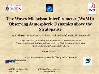
Interferometry is the applied science of combining two or more input points of a particular data type. In optics, to form a greater picture based on the combination of the two sources. In astronomy (such as with the Keck telescopes), this is used to combine light from two or more telescopes to obtain measurements with higher resolution than could be obtained with either telescope individually.
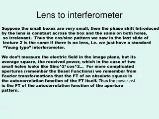
interferometer An interferometer works on the principle that two waves that coincide with the same phase will amplify each other while two waves that have opposite phases will cancel each other out. The interferometer was initially built to work with extended sources. In that case the interference phenomena are explained by the amplitude division.
Michelson designed an interferometer to determine the wavelength of light. Here the basic building blocks are a monochromatic source (emitting light waves), a detector, two mirrors and one semitransparent mirror (often called beam splitter).
M1’ M2 x2 x1 x2 M1
Condition for destructive interference 2dcos = (n + ½ ) Where d = x1~ x2 Condition for constructive interference will be 2dcos = n
Mirrors M1 and M2 are perpendicular to each other and the semi-reflecting face of the separator is tilted at 45° with respect to the normals to M1 and M2. The observation screen is situated along the plane xOy, and the Oz axis coincides with the axis of mirror M.
The virtual image S' of source S in the mirror made up of the "forward" semi-reflecting face of the separator, and then the virtual image M' of the M1 mirror in relation to the back semi-reflecting face of the separator. source S' was lighting up the parallel faced air slide of thickness e made up by mirror M2 and the image M'1 of mirror M1.
Let S1 and S2 be the images of S' through M'1 and M2 mirrors. We obtain a system of two coherent sources located one behind the other on the Oz axis and such that S1S2 = 2e
Path difference = 2dcos
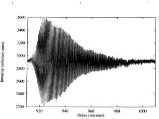
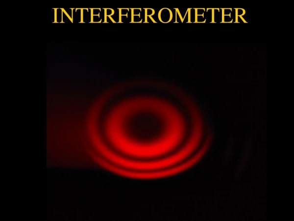
If the distance distances of the two mirrors M1 and M2 From the glass plate are x1 and x2 then to eye the waves emitting from the source will appear to get reflected from Two mirrors M1’and M2 and are separated by distance x1x2. if we use an extended source no definite pattern Will be obtained on the photographic plate placed at eye. If we use at a camera focused for infinity then on the Focal plane we will obtained circular fringes and each circle corresponds to a definite r. Now the extra path that one of the beams will traverse will Be 2(x1x2) and for condition for dark ring 2dcosr = m
cm and d = .025 cm then the angles r Where the dark fringes occur are For = r= 0,2.56, 3.62, 4.44,5.13,5.73,6.28….. m= 1000,999,998,997….. If d=.0025 r= 0, 8.11,11.48,14.07,16.26…. m=100,99,98,97…. So as d decreases the fringes will appear to collapse at the centre. In d slightly decreases then let from .025 to .024999 then r=2.51,3.59,4.41…. m=999,998,997….. Here m=1000 disappears
Further as d decreses the fringe pattern tends to collapse towards the centre. If n fringes collapse to the Centre as the mirroe moves M2 moves by a distance d0 Then 2d=m 2(d-d0)= (m-n) so
Basically, the system consists in a separating slide one face of which has a semi-reflective metallic coating. An incident ray from the extended source S is partially reflected towards mirror M2 and partially transmitted towards mirror M1. We noticed in the preceding figure that the path of ray (1) comprises three crossings of the separator while that of ray (2) only one crossing.
To re-establish equality of optical paths in the glass whatever the incidence and the wave lengths of the radiations used, we insert along path (2), parallel to the separator, a compensating slide C identical to the separator.
x1 x2 x1 M’1
Interferometer produces interference fringes by splitting a beam of monochromatic light so that one beam strikes a fixed mirror and the other a movable mirror. When the reflected beams are brought back together, an interference pattern results.
The planes of mirrors M1 and M2 should be made perfectly perpendicular to each other. Compensating lens is necessary for white light fringe. Always circular fringes are obtained in this Interferometer.
When M’1 AND M2 coincide the path difference Is zero and the field of view is perfectly dark.
In the setup presented in diagram 10, the mirrors are not perpendicular to each other anymore. They have moved by a small angle beta/2 in the same direction relatively to their optical contact position (IA1=IA2). Source S is estimated to be punctual and monochromatic.
M2 M2 M’1 M’1