Download
1 / 74
840 likes | 1.2k Views
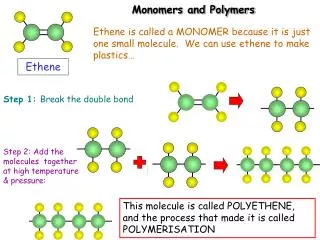
Electronic and Optoelectronic Polymers. Wen-Chang Chen Department of Chemical Engineering Institute of Polymer Science and Engineering National Taiwan University. Outlines. History of Conjugated Polymers Electronic Structures of Conjugated Polymers Polymer Light-emitting Diodes

E N D
Electronic and Optoelectronic Polymers Wen-Chang Chen Department of Chemical Engineering Institute of Polymer Science and Engineering National Taiwan University
Outlines • History of Conjugated Polymers • Electronic Structures of Conjugated Polymers • Polymer Light-emitting Diodes • Polymer-based Thin Film (or Field Effect) Transistors • Polymer-based Photovoltaics • Polymers for Memory devices
What’s Transistor? Transistor • A device composed of semiconductor materials that amplifiers a signal or opens or close circuit. • The key ingredient of all digital circuits, including computers. • Today’s microprocessors contains tens of millions of microscopic transistors. Field-Effect Transistor • A voltage applied between the gate and drain controls the current flowing between the source and drain
What’s Transistor? Field effect transistor works like a drain
Organic Thin Film Transistors (OTFTs) Organic transistors are transistors that use organic molecules rather than silicon for their active materials. These active materials can be composed of a wide variety of molecules. Advantages • Compatibility with plastic substances • Lower-cost deposition process such as spin coating, printing, evaporation • Lower temperature manufacturing (60-120oC) Disadvantages • Lower mobility and switching speeds compared to silicon wafers
Subjects of the Polymer Optoelectronic Device Polymer Solar Cells Polymer Light-emitting Diodes Polymer Thin Film Transistors
Integrated Optoelectronic Devices Based on Conjugated Polymers Sirringhaus H., Tessler N., Friend RH, Science 1998
Optoelectronic Polymer Lab, NTU All Organic Thin Film Transistors (OTFT) Key Materials for OTFT: (1)Active Organic Layer: Organic Semiconductor (2)Source/drain electrodes: Electrical Conducting Materials (PEDOT:PSS for organic case) (3)Gate Dielectrics: Organic polymers (4) Substrate: Highly thermal stable and transparent polymer, e.g., PET, PSF, etc.
Progress on Flexible Organic Display Devices Reference:Science, 290, 2123 (2000)) Reference:Synthetic Metals 145, 83-85(2004) In an active Matrix each pixel contains a light-emitting diodes (LED) driven by a Field-effect transistor (FET). The FET performs signal processing while the LED converts the electrical signal processing into optical output.
Applications of OTFTs Flexible TFT arrays enabling technologies for a whole range of applications
Important Performance Parameters What’s important? • Conduction at the semiconductor dielectric interface • Contacts- injection of charges • Electronic and ambient stability • Fabrication technology Requirements for high performance OTFTs • High Mobility • High On/Off Ration • Low Threshold Voltage • Steep Sub-threshold Slope
Polymer Field Effect Transistors Vd > 0 L W Source Drain - - - - - - - - - - - - - + + + + + + + + + + + + Vg > 0 Why Polymer? • Printability • Flexibility • Low cost & weight • Easy fabrication Polymer Semiconductor Dielectric Layer Substrate/Gate Electrode Architecture of transistor device What’s important? Requirements for high performance • Conduction at the semiconductor dielectric interface • Contacts- injection of charges • Electronic and ambient stability • Fabrication technology • High mobility (>0.1 cm2/VS) • High On/Off current Ratio (>104) • Low Threshold Voltage (within ±5 V) 13
Operation Energy Diagram and Important Parameters Field Effect Mobility (μ) How strongly the motion of an electron or hole is influenced by an electric field The Slope of ID1/2-VG @ saturation region On/Off Current Ratio (Ion/Ioff) (a)Off :the state of a transistor is then on voltage is applied between the gate and source electrode (b) On:drain and source current increases due to the increased number of charge carriers Mobility (a Si-H electron μ~1cm2/VS) Ion/Ioff current ratio (diving circuits in LCD Ion/Ioff >106) P type N type Electron transport Hole transport
Working Principle of OTFTs VTh Threshold Voltage Vd Drain Voltage Vg Gate Voltage Id Drain Current L Channel length W Channel width Linear regime Start of saturation regime at pinch-off Saturation regime
Current-Voltage (I-V) Characteristics Transfer (Id-Vg) Curve Performance Parameters at saturation region Field Effect Mobility (μ) [cm2/VS] Threshold Voltage (VTh) On/Off Current Ratio (Ion/Ioff) Sub-threshold Slope (SS)
Current-Voltage (I-V) Characteristics X=0 to L, V(x)= O to Vds Linear region Vds << Vg Saturation region Vds ~ Vg - VTh
Current-Voltage (I-V) Characteristics Output (Id-Vd) Curve
Materials for OTFTs Semiconductor Layer • Organic S.C. Small molecules (ex: pentacene, oligothiophene) Conjugated polymers (ex: P3HT, F8T2) • Inorganic S.C. (ex: a-Si, Zinc oxide) Insulator Layer • Organic Dielectric (ex: Polyimide, PMMA, PVP) • Inorganic S.C. (ex: SiO2, TiO2, Al2O3) Electrode • Metal (ex: Au, Ca) • Conjugated Polymer (ex: PEDOT:PSS)
Materials Requirements of Organic Semiconductors for OTFT • Target: > 1 cm2/Vs on/off ratio >106 for n type or p/n type Organic Semiconductors • Conjugated π-Electron System High Electron Affinity( for n type) or Ambipolar Characteristics (for p/n type) • Good Intermolecular Electronic Overlap chemical bonding between molecules, molecular symmetry, the symmetry of the crystal packing…. • Good Film Forming Properties polycrystalline film be highly oriented so that fast transports direction in the grains lie parallel to the dielectric surface • Chemical Purity charge trapping sites, dopants (increase the conductivity in off state) • Stability device operation (Threshold Voltage Shift), air stability(O2, H2O)
Evolution of The OTFT mobility for P type or N type Semiconductors P type mobility N type mobility 1-5~ 10-3 cm2/VS 1~ 10-5 cm2/VS mobility (a Si-H μ~1cm2/VS) Adv Mater 2002, 14, 4436
Characteristics of Organic Semiconductors • P type or N type • Charge transport by hole (Low IP) or electron (High EA) • Applications • Light emitting diode, photoconductor, thin film transistor, sensor (PH or gas), solar cell, photovoltaic device…
Structures of P-Channel Semiconductors with TFT Characteristics • Heterocyclic Oligomers • Two dimensional Fused Rings • Linear Fused Rings • Polymeric Semiconductors Acc Chem Res 2001, 34, 359
Structures of P-Channel Semiconductors with Known TFT Characteristics( Dimitrakopoulos and Malenfant, Adv. Mater.2002) Mobility in the range of 10-3 ~ 1-5 cm2V-1S-1 mobility (a Si-H μ~1 cm2/Vs)
Materials Requirements for n-Channel Organic Semiconductors • Conjugated π-Electron System with High Electron Affinity (EA > 3.0 eV) • Good Intermolecular Electronic Overlap chemical bonding between molecules, molecular symmetry, the symmetry of the crystal packing…. • Good Film Forming Properties polycrystalline film be highly oriented so that fast transports direction in the grains lie parallel to the dielectric surface • Chemical Purity charge trapping sites, dopants • Stability device operation (Threshold Voltage Shift), air stability(O2, H2O) Chem. Mater. 2004, 16, 4436
Enhancement on the OTFT Characteristics • Materials issues • Materials Design and Preparation (HT%, regioregular, repeating conjugated unit, substituent, synthesis method, refinement) • Key materials Optimization (gate, source, drain, substrate, dielectric) • TFT Structures • Chemical Treatment on dielectric film surface ( silane layer pretreatment, SAMs thiol-based chemical modified contact) • Modifying the TFT structure (bottom contact or top contact) • Processing Optimization • Organic layer deposition (i) vacuum evaporation (ii) spin coating, solution casting, printing • Controlling the deposition parameters (aging, deposition rate, anneal process, solvent quality, channel length, channel dimension, deposition thickness, solvent evaporation temperature)
Structures of n-Channel Semiconductors with known TFT Characteristics( C. D. Frisbie and coworkers, Chem. Mater. 2004) • Metal-Phthalocyanines ~ 0.6 cm2V-1S-1 • Addition of Electron Withdrawing Groups (cyano, perfluoroalkyl) to p Type Cores 10-4 ~ 0.1 cm2V-1S-1 • Perylene or Naphthalene Derivatives 10-4 ~0.6 cm2V-1S-1 • C60 ~ 0.3 cm2V-1S-1 10-1 ~ 10-5 cm2/VS Need to develop polymer semiconductors with high electronic mobility(>1 cm2/Vs)!
Optoelectronic Polymer Lab, NTU Introduction to PTCDA and PTCDI-R R= C8H17 R= CH2C6H4CF3
Optoelectronic Polymer Lab, NTU Air stable PTCDI-R or NTCDI-R NTCDI-C6H4CF3 NTCDI-C8H17 • Less negative reduction potential of fluorinated chains may be stabilized during operation in air • Denser packing of fluorinated chains could be more permeable to oxygen and water NTCDI-CH2C7F15 H.E. Katz et al., Nature 2000, 404, 479 H.E. Katz et al., JACS 2000, 122, 7787
Optoelectronic Polymer Lab, NTU Introduction to PTCDI-R Single-crystal-like packing π stacking occurs parallel to the substrate surface
Optoelectronic Polymer Lab, NTU Why Using PTCDI-R as N Type OTFTs • Single-step synthesis • Impart additional electron withdrawing character to the conjugated backbones to stabilized electron injection. • Provide screening against penetration of environmental contaminants (H2O, O2..)into the channel region. • The side group could induce a more favorable packing geometry that increases intermolecular overlaps or reduces phonon scattering.
Mobility for Semiconducting Polymers HOMO / LUMO (eV) Hole / Electron mobility (cm2V-1S-1) Ca s-d electrode RH Friend et al, Nature2005, 434, 194
Comparable Electron & Hole Mobility for OTFT: Donor-Acceptor Systems
Donor-AcceptorConjugated Polymer Semiconductors with High FET Mobility (Literature~2009) Hole/Electron mobility 1.4 cm2/VS 0.1 cm2/VS 0.1 cm2/VS Adv. Mater. 2009, 21, 209 Adv. Mater. 2008, 20, 2217 0.2 cm2/VS 0.1 cm2/VS J. Mater. Chem. 2009, 19, 591 J. Am. Chem. Soc. 2008, 130, 8580 0.85 cm2/VS Nature. 2009, 457, 679 0.2 cm2/VS J. Am. Chem. Soc. 2009, 131, 2521 Q: Could we develop newsolution-processable semiconducting polymerswith mobility > 1 cm2/Vsandgood environmental stability? 38
Conduction Mechanism in OTFT Channel Charge carrier mobility is dependent on molecular order within the semiconducting thin film Current modulation is achieved by electric field-induced charge build-up at the interface between the organic semiconductor and the insulator IBM J. Res. and Develop.2001, 45, 11
Charge Transport in Organic Crystal Limit of mobility in organic single crystal at room temperature is due to the weak intermolecular interaction forces (van der waals interaction) of 10 kcal/mole (cf 76 kcal/mole for Si covalent bond) Fi >> Fv Fi ~ Fv Band transport • Strong π-orbital overlap • Band transport • Negative temp coefficient • Weak π-orbital overlap • Hopping transport • Positive temp coefficient Hopping transport Fi intermolecular interaction force ; Fv thermal vibration force
Charge Transport in Polymer Intra-Molecular Soliton Propagation :μ~1000 cm2/VS Inter-Molecular Hopping transport :μ~10-2cm2/VS It is important to increase molecular ordering to obtain high mobility in OTFT devices
Organic & Inorganic Semiconductors Organic Semiconductor Inorganic Semiconductor • Strong covalent bonds • ρ-bond • Only crystal property • Band type charge transport dominant • High mobility and large mean free path • Weak Van der Waals interaction forces • π-bond overlapping • Molecular gas property (molecule’s identity) • Hopping type charge transport dominant • Low mobility and small mean free path
Bipolar OTFT- Organic Semiconductors in Interfacial Properties Idealized energy level diagram of OTFTs P- & N- Channel OTFT Operation
Scattering Mechanism in Thin Film For high mobility • Flat & clean surface • Large grain • No doping
Operation Energy Diagram and Important Parameters Field Effect Mobility (μ) How strongly the motion of an electron or hole is influenced by an electric field The Slope of ID1/2-VG @ saturation region On/Off Current Ratio (Ion/Ioff) (a)Off :the state of a transistor is then on voltage is applied between the gate and source electrode (b) On:drain and source current increases due to the increased number of charge carriers Mobility (a Si-H electron μ~1cm2/VS) Ion/Ioff current ratio (diving circuits in LCD Ion/Ioff >106) P type N type Electron transport Hole transport
Enhancement on Performance of OTFTs • Chemical surface treatment on dielectric film surface or electrode (SAMs silane layer pretreatment, plasma treatment) • Modify the TFT structure (bottom contact or top contact) • Control the processing parameters (deposition rate, anneal process, solvent power, channel dimension, deposition thickness, heat treatment, film forming method) • Choose materials (gate, source, drain, substrate, dielectric) • Organic P3HT selection (HT% regioregularity, molecular weight, substituent, synthesis method, refinement)
Surface treatment on Inorganic Dielectric Self-Assembly Monolayer (SAM) • Hexamethyldisilazene (HMDS) • Octadecyltrichlorosilane (HMDS) • Other silanes • Alkanephosphonic acid • Increased grain boundary of OSC • Hydrophilic to hydrophobic attachment (smooth surface) • Increasing molecular ordering • Obtain improved OTFT characteristics
Surface Treatment on Inorganic Dielectric Self-Assembly Monolayer (SAM) Adv. Funct. Mater. 2005, 15, 77
Chemical Treatment on Dielectric Surface Plasma pretreatment Plasma treatment Un-treatment Plasma treatment RMS roughness: 0.8 ~ 1.3 nm RMS roughness: 0.3 ~ 0.5 nm untreatment Higher mobility after plasma treatment Synth Met. 2003, 139, 377
Dielectrics Requirements for OTFT Dielectrics • High dielectric constant for low-voltage operating • Good heat and chemical resistance • Pinhole free thin film formability with high breakdown voltage and long term stability • Comparable with organic semiconductor in interfacial properties Polymeric Dielectrics Adv. Mater. 2005, 17, 1705