Download
1 / 46
460 likes | 667 Views
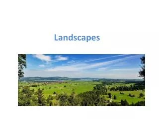
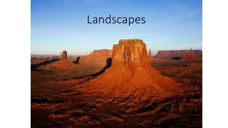
Rendering of Realistic Landscapes. K. H. Ko Department of Mechatronics Gwangju Institute of Science and Technology. September 20, 2012. Introduction. Creating detailed three dimensional landscapes manually is a costly and slow process. Automatic generation of landscapes is needed.

E N D
Rendering of Realistic Landscapes K. H. Ko Department of Mechatronics Gwangju Institute of Science and Technology September 20, 2012
Introduction • Creating detailed three dimensional landscapes manually is a costly and slow process. • Automatic generation of landscapes is needed. • Features in a landscape • Terrain with a varying topology and surface structure : the basis • Plants : forests, fields • Individual buildings, cities, roads, infrastructure • Rivers, lakes, seas, sky, clouds, the sun, stars • Animals and people, etc.
Introduction • To create a realistic landscape • It is not enough that the elements making up the landscape look realistic. • They should also be placed naturally in relation to each other. • Mimicking the way real landscapes are structured. • Ecotopes provide a way to achieve this. • A consistent landscape with variation both at local and global scales is more interesting than a completely random or homogeneous landscape.
Introduction • Applications • Flight simulators, computer games, visualization in architecture, land use planning tools, geographical visualization, landscape design, background generation for movies, etc. • Dynamic and interactive landscapes but could be artificial • Computer games • Static but accurate landscape • Geographical information system
Procedural vs. Declarative • Declarative Approach • Define every details and properties of every object in the landscape. • The designer has absolute control over the landscape. • It requires a huge amount of storage space. • Creating a landscape takes time. • It is used for real world geographical system. • Conformance to the real world geography is important. • The terrain height and object placement information can be obtained from measurement data.
Procedural vs. Declarative • Procedural Approach • It generates the landscape using algorithms that produce varying, natural looking data. • This approach can be used if the landscape does not have to match any real life location. • Almost no input data is required. • Specialized algorithms are used. • Small disk storage and minimum work
Hybrid • Both the procedural and declarative methods are combined. • Use the procedural approach by default • Allow exact definitions in places • The landscape designer can accurately specify details where they are needed.
Ecotopes • Different areas in an extensive natural landscape may have very different appearances. • Rocky ground, forests, lakes, etc. • Ecotopes are a way to implement this kind of variation. • Ecotopes provide a flexible framework that can be used to implement both macro and micro scale features • Macro scale features: forests • Micro scale features: tall grass • They give landscape designers both controls over the characteristics of different types of landscape, as well as control over where to apply what type of landscape.
Ecotopes • Landscape parameters of an ecotopes • Height functions • A number of different plant species and their densities • Rain amounts which affect the number of rivers and lakes generated. • Population density • Number of buildings • Etc.
Ecotopes • Distribution Properties of Ecotopes • Terrain elevation, relative elevation, slope angle, proximity to sea, proximity to a river or lake, etc. • Randomly generated noise function
To Create a Landscape… • Terrain • Plants • Trees, grass, etc. • Buildings • Cities • The Sky • Clouds, weather, climate, atmosphere, celestial bodies, etc.
Terrain • It is the basis for a landscape, i.e. the shape of the ground. • For efficiency in modeling and rendering the ground, we may assume that • The ground surface has no overhangs. • Any ray from the center of the planet intersects the planet surface exactly once. • Under this assumption, the ground shape can be defined by a ground height function. • When modeling and rendering only a small part of the planet surface, we treat the surface as planar.
Terrain • For rendering a ground surface, it is often practical to only store samples of the ground height function at some intervals. • Called an elevation map or height map. • If the height is encoded as colors, it can be stored as an image.
Random Terrain Generators • The simplest way is to assign each position on the ground a random height. • The result of that bears little resemblance to natural terrain. • In fact the natural ground is more or less continuous, while still varying in height in complex ways depending on the position.
Random Terrain Generators • Stochastic Subdivision Algorithms • Iterative subdivision with pseudo-random midpoint displacement • Algorithm • The terrain starts with a single large square, with a height value of zero at each corner. • A pseudo-random height offset that is proportional to the size of the square, is added to each corner of the square. • The square is divided into four smaller ones, with the height of each new corner interpolated between the heights of neighboring corners of the original square. • The algorithm is repeated from step 2 for each square, until the squares are at the desired LOD.
Random Terrain Generators Height Map 3D Rendering
Random Terrain Generators • Stochastic Subdivision Algorithms • Drawbacks • It often produces unnatural looking regularities (sharp ridges or peaks) • The random variation varies linearly with the scale of the features. • In nature terrain the amplitude of height variation does not depend linearly on the scale of the features.
Random Terrain Generators • Stochastic Subdivision Algorithms • Diamond Square Subdivision • The algorithm divides a square into four smaller squares rotated 45 degrees in relation to the original square. • It eliminates some of the more visible artifacts, but has some quite noticeable point-like artifacts of its own.
Random Terrain Generators • Stochastic Subdivision Algorithms • Offset square subdivision • It can avoid most of the artifacts, but with somewhat increased performance cost. • The smaller squares are offset from the larger square corners, and the initial values for the smaller square corners are calculated with a weighted average. • More smooth terrain
Random Terrain Generators • Faulting Algorithms • They generate fractal data by repeatedly dividing the terrain with a faulting edge. • Raising the terrain on one side of the edge and lowering it at the other to achieve a height difference along the faulting edge. • Over time the height difference is reduced and when it arrives at zero the terrain is ready.
Random Terrain Generators • Faulting Algorithms • Very slow • Not suitable for applications where a small visible area of a larger terrain needs to be generated.
Random Terrain Generators • Perlin Noise • It approximates smooth white noise of a given frequency in one or more dimensions. • Combining several layers (called octaves) of noise at different frequencies and amplitudes, a natural looking fractal noise can be obtained. • This combined noise is called Perlin turbulence, or just Perlin noise. One layer
Random Terrain Generators • Perlin Noise • The characteristics of a terrain height field can be adjusted by changing the number of octaves, the amplitude and frequency of each octave.
Random Terrain Generators • Perlin Noise • It does not have any regular visible artifacts and is fast. • It is a popular choice for random terrain generation. • One variation of Perlin turbulence is the ridged multi-fractal noise. • It uses absolute value functions to produce features with a ridged appearance. • Approximate eroded mountain ranges.
Random Terrain Generators • Successive Mass Deposit • It is based on the idea of repeatedly adding some mass at a random location of the terrain. • The mass has a Gaussian distribution profile around the addition point. • The addition is repeated with successively smaller masses.
Geological Effects on the Terrain • A height field that statistically resemble the real landscape topographies visually lacks many of the distinct geological features found in real world landscapes. • The result of various geological processes • Topology building processes • Move the planet crust or allow magma to rise to the surface. • Erosive processes • Wear down the planet crust to progressively more fine grained particles. • Transport these particles and deposit them in new places.
Terrain Level of Detail • Level of Detail For Terrain Visualization • Easier than arbitrary 3D models • The geometry is more constrained, normally consisting of uniform grids of height values. • More specialized and potentially simpler algorithms could be possible. • More Difficult • It is possible to have a large amount of terrain visible at any point. • LOD techniques are critical • Terrain meshes can be extremely dense. • The U.S. Geological Survey data: 30-arc-second resolution (roughly 1 kilometer at the equator) – 933 million points, 1.8 billion triangles over the entire planet.
Algorithms for Terrain(Top Down or Bottom Up) • Top Down: Subdivision or Refinement methods • Begin with two or four triangles for the entire region. • Progressively add new triangles until the desired resolution is achieved. • Bottom Up: Decimation or Simplification • Begins with the highest-resolution mesh • Iteratively removes vertices from the triangulation until the desired level of simplification is gained.
Algorithms for Terrain(Top Down or Bottom Up) • Bottom-up approaches tend to be able to find the minimal number of triangles required for a given accuracy. • However, they necessitate the entire model being available at the first step. • Higher memory and computational demands.
Algorithms for Terrain(Top Down or Bottom Up) • Bottom-up approaches are almost always used during the initial offline hierarchy construction. • At run-time, a top-down approach might be favored. • It offers support for view culling.
Algorithms for Terrain(Regular Grids and TINs) • The use of regular grid height fields • Regular (uniform) grids use an array of height values at regularly spaced x and y coordinates. • Triangulated Irregular Networks (TINs) • TINs allow variable spacing between vertices.
Algorithms for Terrain(Regular Grids and TINs) • Advantages of TINs • They can approximate a surface to a required accuracy with fewer polygons. • Large flat regions are represented with a coarse sampling. • Higher sampling is reserved for more bumpy regions. • They offer great flexibility in the range and accuracy of features. • Ridges, valleys, coastlines, caves, etc. • Disadvantages of TINS • They make implementing related functions (view culling, terrain following, collision detection and dynamic deformation) more complex. • Due to the lack of a simple overarching spatial organization. • The applicability of TINs to run-time view-dependent LOD is less efficient than regular gridded systems.
Algorithms for Terrain(Regular Grids and TINs) • Disadvantages of Regular Grids • They tend to be far less optimal than TINs. • The same resolution is used across the entire terrain. • Advantages of Regular Grids • They are simple to store and manipulate. • They are easily integrated with raster databases and file formats • DEM, DTED, GeoTIFF, etc. • They require less storage for the same number of points. • An array of z values needs to be stored rather than full (x,y,z) coordinates.
Algorithms for Terrain(Regular Grids and TINs) • For these reasons, many contemporary terrain LOD systems favor regular grids over TINs.
Algorithms for Terrain(Quadtrees and Bintrees) • For multiresolution representation we use quadtrees or bintrees. • Quadtree Structure • A rectangular region is divided uniformly into four quadrants. • Each of these quadrants can then be successively divided into four smaller regions.
Algorithms for Terrain(Quadtrees and Bintrees) • A binary triangle tree structure works the same way as a quadtree. • But it segments a triangle into two halves. • The root triangles is normally defined to be a right-isosceles triangle. • The subdivision is performed by splitting this along the edge formed between its apex vertex and the midpoint of its base edge.
Algorithms for Terrain(Quadtrees and Bintrees) • Advantages of Bintrees • They make it easy to avoid cracks and T-junctions. • Exhibit the useful feature that triangles are never more than one resolution level away from their neighbors. Subdivision progression example. The root triangle is A
Algorithms for Terrain(Tears, Cracks and T-Junctions) • When adjacent triangles exist at different levels of detail, • It is possible to introduce cracks along the edge. • The higher LOD introduces an extra vertex that does not lie on the lower LOD edge. • When rendered, these cracks can cause holes in the terrain, allowing the background to peak through.
Algorithms for Terrain(Tears, Cracks and T-Junctions) • When adjacent triangles exist at different levels of detail, • Another undesirable artifact is the T-junction. • It is caused when the vertex from a higher LOD triangle does not share a vertex in the adjacent lower LOD triangle. • It can result in bleeding tears in the terrain and visible lighting and interpolation differences across the edges.
Algorithms for Terrain(Tears, Cracks and T-Junctions) • How to deal with cracks… • The triangles around the crack are recursively split to produce a continuous surface. • It is often used in bintree-based system.
Terrain Texturing • After generating and rendering the geometry of the landscape, we still need to texture it. • It means covering the triangles making up the landscape with images of the ground in that area. • Method 1 • Just repeat a texture over the landscape. • Results in visible tiling artifacts, and a quite boring landscape.
Terrain Texturing • Method 2 • Use a number of different textures which match each other along some edges. • We fill the plane with these textures, making sure adjacent texture edges match each other. • Still somewhat boring landscape. • Method 3 • To make the landscape more varying, we can texture different ecotopes with different textures. • Mountain tops and hill slopes can be bare while valley floors can be more lush. • We blend between different textures based on the strength of different ecotopes.
Terrain Texturing • Texture Blending • Instead of simply blending between different terrain textures, more natural edges can be achieved by using custom textures for the edges between textures.
Terrain Texturing • Texture Blending • The edge tiles can be drawn so that the underlying area is left transparent, allowing the topmost texture to be simply drawn on top of underlying textures.