Download
1 / 45
470 likes | 664 Views
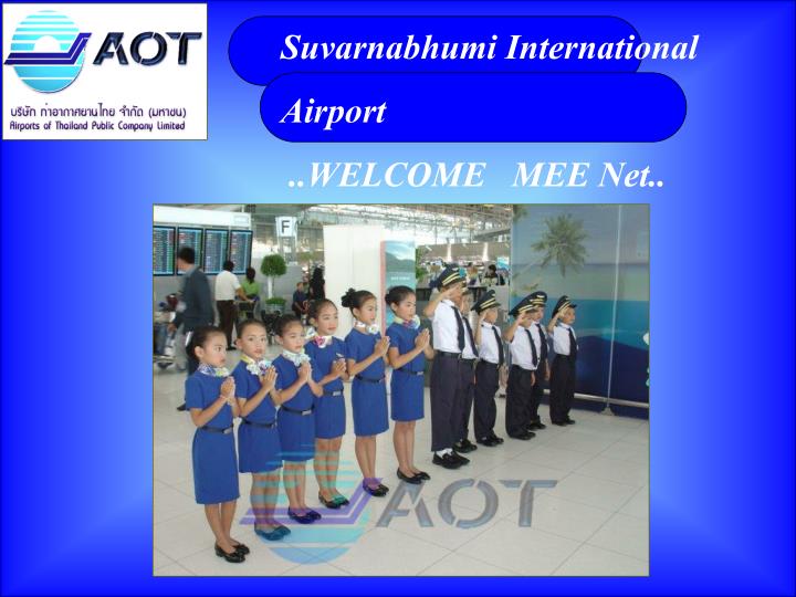
Suvarnabhumi International Airport .. WELCOME MEE Net. SUVARNABHUMI INTERNATIONAL AIRPORT. SUVARNABHUMI AIR CONDITIONING SYSTEM. SUVARNABHUMI AIR CONDITIONING SYSTEM. BUILDING CONFIGURATION

E N D
Suvarnabhumi International Airport ..WELCOME MEE Net.. MJTA Consortium
. SUVARNABHUMI INTERNATIONAL AIRPORT MJTA Consortium
SUVARNABHUMI AIR CONDITIONING SYSTEM • BUILDING CONFIGURATION • The Terminal building requires to have large hall area without concrete pole or with minimal concrete pole for passengers’ convenience. For maximum passengers comfort with ease of traveling within the airport compound, the building comprise of two sectors, the Terminal and Concourse building.The Concourse building is for airplane connection to boarding bridges. The Terminal building is for handling departure and arrival passengers. • For energy saving purpose, the airconditioning will be provided only from floor level to 3 or 4 meter above the floor since passengers will not stay higher than 2 meters above the floor MJTA Consortium
SUVARNABHUMI AIR CONDITIONING SYSTEM • BUILDING SIZE • Concourse • Width40.50 m. Length 3,123 m. • Hight 23.60 m. • Terminal • Width 108 m. Length 441 m. Hight 40 m. MJTA Consortium
SUVARNABHUMI AIR CONDITIONING SYSTEM • AREA FOR AIR CONDITIONING • Concourse • 248,445 SQ.M. • Terminal • 119,906 SQ.M. TOTAL OF 368,351 SQ.M. MJTA Consortium
CONCEPTUAL DESIGN FOR ENERGY SAVING OF SUVARNABHUMI AIR CONDITIONING SYSTEM • Usage of direct sun light with minimal electrical lamps during day time. • Air conditioning will be provided only from floor level to 3 or 4 meter above the floor to reduce the air conditioning loadby means of Stratification technique. This technique use Radiant Floor Cooling together with Recirculated Air Cooling System. 3. Control intake fresh air for continual changing number of passengers. MJTA Consortium
CONCEPTUAL DESIGN FOR ENERGY SAVING OF SUVARNABHUMI AIR CONDITIONING SYSTEM 4. Adjust Variable Chilled Water Volume for continual changing cooling load. • UseChilled Water Temperature Difference ( delta T ) larger than normal conventional typewhich will require lesser pipe size andflow rate, thus reduced the pump size and energy required. • Reduce make up water of Cooling Tower by way of water filter instead of bleed-off 7. Reduce solar heat gain through glass by way of using Frit, a small circular pad, spread evenly on glass which help reduce theSolar Factor MJTA Consortium
CONCEPTUAL DESIGN FOR ENERGY SAVING OF SUVARNABHUMI AIR CONDITIONING SYSTEM พลังงาน 8. Reduceinfrared radiation from ceiling and wallby way of applyingLow-E Infrared Hard Coating on ceiling and wall. • Reduce convective heat gainfrom electrical lamps since the heat gain will be combined with hot air above stratification level which will cause no effect to passengers. • Reduce radiation heat gain by way of using radiant floor cooling together with conventional air conditioning system. MJTA Consortium
Air Conditioning System MJTA Consortium
Radiant Floor Cooling Cooling tube to Diffuser Header Poly Etelene 1 header=10 loops Diffuser MJTA Consortium
SUVARNABHUMIINTERNATIONAL AIRPORT. Radiant Floor Shop Drawing: Configuration Detail Drawing. 12 MJTA Consortium
SUVARNABHUMIINTERNATIONAL AIRPORT. Radiant Floor Shop Drawing: Floor Plan 13 MJTA Consortium
SUVARNABHUMIINTERNATIONAL AIRPORT. VAC System. Temperature Layer 14 MJTA Consortium
SUVARNABHUMI AIR CONDITIONING SYSTEM • Design Criteria • Ambient Temp. 35C db • 28C wb • Indoor Temp. 24C±1 db • Relative Humidity 55+5% RH • Lighting: Circulation, Holdroom 10 W/m2 • Office 15 W/m2 • Retail 35 W/m2 MJTA Consortium
SUVARNABHUMI AIR CONDITIONING SYSTEM • Design Criteria • Outside Air: Circulation, Holdroom 17 m3/hr/person • Office 34 m3/hr/person • Retail 26 m3/hr/person • Passengers: Terminal + Concourse 22,879 persons (30 MAP)(Peak Hour) 27,379 persons (45 MAP) • OA total 506,011 m3/hr (30 MAP) • 582,511 m3/hr (45 MAP) MJTA Consortium
SUVARNABHUMI AIR CONDITIONING SYSTEM • Design Criteria • Total Cooling Capacity • 41,666 KW = 11,850 Tons (30 MAP) • 43,238 KW = 12,297 Tons (45 MAP) MJTA Consortium
SUVARNABHUMI AIR CONDITIONING SYSTEM • AOT purchase chilled water fromDCAP (Districted Cooling System and Power Plant Company Limited). DCAP has installed 8 ABSORPTION CHILLERS atCENTRAL PLANT located within Parking building next to the Terminal building. DCAP installed 4 ABSORPTION CHILLERS (DOUBLE EFFECT TYPE )on each plant (EAST and WEST PLANT) andeach absorption chiller has the capacity of2,100 TR (norminal) and can produce 706 m3/hr (196.11 L/S) chilled water at return temp. of14 C and supply temp. of 5 C MJTA Consortium
SUVARNABHUMI AIR CONDITIONING SYSTEM • 4 Absorption Chiller Cooling capacity@2100 TR (7,386 kW) • = 8,400 TR (29,544 kW) • 4 Secondary chilled water pumps @ 706 m3/hr (196.11 L/S) • = 2,824 m3/hr (784.44 L/S) • Supply Temp. 5o C • Return Temp. 14o C • TOTAL COOLING CAPACITY OF EAST AND WEST PLANTS • = 16,800 TR (59,088 kW) MJTA Consortium
SBIA : TERMINAL COMPLEX • 30 MILLION ANNUAL PASSENGER • REDUCED CONCORSE WIDTH 4.35M • AND • REVISED MATERIAL OF CONSTRUCTION MJTA Consortium
WATER SIDE PEAK COOLING LOADS SUMMARY30 MAP • A) Heat Transmission + Electrical Load at Peak Hour • East Concourse Building 7,464 kW. • West Concourse Building 7,381 kW. • Terminal Building 4,875 kW. • Jetbridge East Concourse 617 kW. • Jetbridge West Concourse 559 kW. • Sub Total A) = 20,896 kW. MJTA Consortium
WATER SIDE PEAK COOLING LOADS SUMMARY30 MAP(Cont’d) • B) Occupancy and O.A Load • B.1 Officers + Employees + • Visitors + Meeters = 13,879 Persons • Total Adjusted Heat Gain 130 W/Person; • 13879 x 130/1000 = 1,804 kW. • Total O.A Supply 353,011 Cubic Meter Per Hour • Total O.A. Load = 1.19 x 353,011/3.6 x (90-51)/1,000 • = 4,551 kW. MJTA Consortium
WATER SIDE PEAK COOLING LOADS SUMMARY30 MAP(Cont’d) • B) Occupancy and O.A Load (Cont’d) • B.2 TPHP of 30 Million Annual Flow as Recommended by FAA is Equivalent to 9,000 persons • TPHP Load of Passenger = 9,000 x 130 / 1,000 = 1,170 kW. • O.A. Load for TPHP = 1.19 x 9,000 x 17 / 3.6 x (90-51) / 1,000 = 1,972 kW. • Sub Total B) = 9,497 kW. MJTA Consortium
WATER SIDE PEAK COOLING LOADS SUMMARY30 MAP(Cont’d) • C) Machine Room Cooling Load • 6 sets AHU Capacity each 142 kW. = 852 kW. • Sub Total C) = 852 kW. • D) PCA. Chiller Heat Rejection • PCA. Chiller Capacity each 350 Ton, 525 HP Motor, Max • Heat Rejection is 1,621 kW. Per set, 6 sets x 1,621 = 9,726 kW. • Sub Total D) = 9,726 kW. • E) Electrical Load • Heat Dissipated from Transformers and LVSB = 695 kW. Sub Total E) = 695 kW. MJTA Consortium
WATER SIDE PEAK COOLING LOADS SUMMARY30 MAP(Cont’d) • SUMMARY Heat Transmission + Electrical Load at Peak Hour = 20,896 kW Occupancy and O.A Load = 9,497 kW Machine Room Cooling Load = 852 kW PCA. Chiller Heat Rejection = 9,726 kW Electrical Load = 695 kW Total Peak Hour Chiller Cooling Capacity = 41,666 kW MJTA Consortium
SBIA : TERMINAL COMPLEX • 45 MILLION ANNUAL PASSENGER • REDUCED CONCORSE WIDTH 4.35M • AND • REVISED MATERIAL OF CONSTRUCTION MJTA Consortium
WATER SIDE PEAK COOLING LOADS SUMMARY45 MAP • A) Heat Transmission + Electrical Load at Peak Hour • East Concourse Building 7,464 kW. • West Concourse Building 7,381 kW. • Terminal Building 4,875 kW. • Jetbridge East Concourse 617 kW. • Jetbridge West Concourse 559 kW. • Sub Total A) = 20,896 kW. MJTA Consortium
WATER SIDE PEAK COOLING LOADS SUMMARY45 MAP(Cont’d) • B) Occupancy and O.A Load • B.1 Officers + Employees + • Visitors + Meeters = 13,879 Persons • Total Adjusted Heat Gain 130 W/Person; • 13879 x 130/1000 = 1,804 kW. • Total O.A Supply 353,011 Cubic Meter Per Hour • Total O.A. Load = 1.19 x 353,011/3.6 x (90-51)/1,000 • = 4,551 kW. MJTA Consortium
WATER SIDE PEAK COOLING LOADS SUMMARY45 MAP(Cont’d) • B) Occupancy and O.A Load (Cont’d) • B.2 TPHP of 45 Million Annual Flow as Recommended by FAA is Equivalent to 13,500 persons • TPHP Load of Passenger = 13,500 x 130 / 1,000 • = 1,755 kW. • O.A. Load for TPHP = 1.19 x 13,500 x 17 / 3.6 x (90-51) / 1,000 = 2,959 kW. • Sub Total B) = 11,069 kW. MJTA Consortium
WATER SIDE PEAK COOLING LOADS SUMMARY45 MAP(Cont’d) • C) Machine Room Cooling Load • 6 sets AHU Capacity each 142 kW. = 852 kW. • Sub Total C) = 852 kW. • D) PCA. Chiller Heat Rejection • PCA. Chiller Capacity each 350 Ton, 525 HP Motor, Max • Heat Rejection is 1,621 kW. Per set, 6 sets x 1,621 = 9,726 kW. • Sub Total D) = 9,726 kW. • E) Electrical Load • Heat Dissipated from Transformers and LVSB = 695 kW. • Sub Total E) = 695 kW. MJTA Consortium
WATER SIDE PEAK COOLING LOADS SUMMARY45 MAP(Cont’d) • SUMMARY Heat Transmission + Electrical Load at Peak Hour = 20,896 kW Occupancy and O.A Load = 11,069 kW Machine Room Cooling Load = 852 kW PCA. Chiller Heat Rejection = 9,726 kW Electrical Load = 695 kW Total Peak Hour Chiller Cooling Capacity = 43,238 kW MJTA Consortium
WATER SIDE PEAK COOLING LOADS SUMMARY30 MAP AND 45 MAP MJTA Consortium
WATER SIDE PEAK COOLING LOADS SUMMARY30 MAP AND 45 MAP (Cont’d) MJTA Consortium
WATER SIDE PEAK COOLING LOADS SUMMARY30 MAP AND 45 MAP (Cont’d) MJTA Consortium
CHILLED WATER PIPE COOLING CAPACITY CHILLED WATER PIPE SCH. 40 COOLING CAPACITY BASED ON MJTA Consortium
CHILLED WATER PIPE COOLING CAPACITY MJTA Consortium
District Cooling System and Power Plant (DCSPP) for Suvarnabhumi International Airport . MJTA Consortium
District Cooling System and Power Plant (DCSPP) • By using natural gas as fuel to generate electricity and use excess heat to produce hot steam as a requirment for absorbtion chiller to produce chilled water for air conditioning purpose. This technology will increase efficiency in generating electricity and chilled water and will also reduce energy required. MJTA Consortium
Airport Electrical Power Distribution MEA 115kV Back Up MTS DCAP Airport Main Transformer 115kV 6.9kV 24kV DCAP In-house use All Area in Airport MJTA Consortium
Chilled Water Distribution Train Station??, Car Park 700RT Train Station 100RT MTB&Concourse 12,600RT AOB 1500RT AIM 200RT AIMS 700RT AOB 500RT Chilled Water Supply from DCAP to ….. DCAP Airport Hotel 700RT Total 19,000RT (29,860RT) Installed TG Catering Facility 5,000RT Airport Hotel 1,500RT MJTA Consortium
Steam Distribution 10barg/185C/8.6t/h DCAP DCAP TG Catering 8barg/175C/3t/h Airport Hotel Airport Hotel MJTA Consortium
ตำแหน่งที่ตั้งของโครงการตำแหน่งที่ตั้งของโครงการ POWER PLANT CHILLER PLANT FOR CATERING CHILLER PLANT FOR PASSENGER TERMINAL MJTA Consortium