Download
1 / 37
370 likes | 619 Views
Abbreviations for integration diagrams. 1. Heat pump 6. Passive cool production unit with cooling controller N6 1.1 Air-to-water heat pump 7. Heating and silent or dynamic cooling 1.2 Brine-to-water heat pump 8. Fan convector with 4-pipe connection

E N D
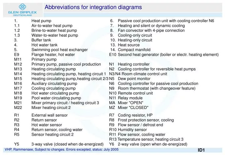
Abbreviations for integration diagrams 1. Heat pump 6. Passive cool production unit with cooling controller N6 1.1 Air-to-water heat pump 7. Heating and silent or dynamic cooling 1.2 Brine-to-water heat pump 8. Fan convector with 4-pipe connection 1.3 Water-to-water heat pump 9. Cooling-only circuit 3. Buffer tank 10. Heating-only circuit 4. Hot water tank 13. Heat source 5. Swimming pool heat exchanger 14. Compact manifold E9 Flange heater, hot water E10 Second heat generator (boiler or electr. heating element) M11 Primary pump M12 Primary pump, passive cool production N1 Heating controller M13 Heating circulating pump N2 Cooling controller for reversible heat pumps M14 Heating circulating pump, heating circuit 1 N3/N4 Room climate control unit M15 Heating circulating pump,heating circuit 2/3 N5 Dew point monitor M16 Auxiliary circulating pump N6 Cooling controller for passive cool production M17 Cooling circulating pump N9 Room thermostat (with changeover feature) M18 Hot water circulating pump N10 Remote control unit M19 Pool water circulating pump N11 Relay module M21 Mixer primary circuit / heating circuit 3 MA Mixer "OPEN" M22 Mixer heating circuit 2 MZ Mixer "CLOSED" R1 External wall sensor R7 Coding resistor, HP R2 Return sensor R8 Frost protection sensor, cooling R3 Hot water sensor R9 Flow sensor / defrost end R4 Return sensor, cooling water R10 Humidity sensor R5 Sensor heating circuit 2 R11 Flow sensor, cooling water R13 Temperature sensor, heating circuit 3 Y5 3-way valve (closed when de-energized)Y6 2-way valve (open when de-energized)
Brine-to-water heat pump, monovalent, 1 heating circuit • Serial buffer tank in the flow line enable conversion to a mono-energetic system • Overflow valve in conjunction with buffer tank and circulation pump (conventional non-electronic control) designed to maintain the minimum heating water flow rate and minimum running time of the compressor • Return temperature control for optimised system temperatures and keeping immersion heater operating periods to a minimum by sensing the actual heat requirement
Brine-to-water heat pump, monovalent, 1 heating circuit, DHW • Call for hot water activated via sensor inside hot water cylinder • Changeover from heating to hot water mode through deactivation of heat circulating pump and activation of hot water circulating pump • Hot water circulating pump and heat exchanger surface area to be dimensioned so that the temperature difference between supply and return is max. 10K • Lower temperature spreads result in higher hot water temperatures
Brine-to-water heat pump, monovalent/mono-energy, 1 HC, DHW • Where an immersion heater is installed in the buffer tank, it must be protected like a heating system in accordance with DIN EN 12828, and the pressure relief valve and expansion vessel have to be fitted directly on the buffer tank.
Compact manifold Brine accessories Compact manifold
Compact Manifold Hot water module Manifold bar Compact manifold assembly with manifold bar and HWM
Brine-to-water heat pump, mono-energy, 2 heating circuits, DHW • Hydraulic decoupling of the heat source and heat distribution circuits by means of a manifold without differential pressure • Secondary heating circuit with mixing valve for the generation of different temperature levels (radiator/underfloor heating circuits) • Call for heat possible via heating circuits 1 and 2 • Activation of heating system circulators of heating circuits 1 and 2 via heat pump controller
Brine-to-water heat pump, monovalent, 2 heating circuits, DHW
Air-to-water heat pump, mono-energy, 1 heating circuit • With air-to-water heat pumps, heat is temporarily extracted from the heating system during the defrost cycle • The buffer tank ensures that defrosting takes place and provides a possibility for installing the immersion heater • Additional shut-off valves with a draining option inside the building ensure that heat pumps installed outdoors can be drained • A frost protection sensor (flow sensor) installed in the heat pump prevents freezing of the heating water in all operating states (heat pump controller must be in operation)
Air-to-water HP, ME, 1 HC, manifold without differential pressure • The manifold without differential pressure ensures a minimum heating water flow rate through the heat pump at all times • A useful feature whenever heat source and heat consuming circuits are (have to be) operated with different volume flow rates
Air-to-water HP, ME, 1 HC, manifold without differential pressure • Circulating pump of the heating circuit 1 is to be dimensioned in accordance with the pressure loss in the heat consuming circuit. • Circulating pump of the main circuit is to be dimensioned in accordance with the pressure loss in the heat pump incl. connecting lines.
Air-to-water HP, ME, 1 HC, manifold without differential pressure
Air-to-water HP, mono-energetic, 2 heating circuits, DHW • A flange heater installed in the hot water cylinder may be used for reheating to reach temperatures above 60°C • Time functions offer the possibility for domestic hot water preparation in accordance with requirements, by means of the heat pump with an option for selective reheating using an immersion heater
Air-to-water HP, bivalent, 1 heating circuit, DHW • The heat pump controller can activate a supplementary heat source when it is required • In the case of heating systems with a constant heating temperature, a controlled mixing of supply and return water is effected via the 4-way mixing valve • An adjustable limit outside temperature permits the second heat source to be activated • A special program is designed to prevent corrosion in older heating boilers
Air-to-water HP, bivalent, 1 heating circuit, DHW • The parallel buffer enables additional heat sources (e.g. solar / wood) to be used for back-up heating and domestic water heating. • Once the buffer tank has been charged, the heat pump is disabled by a thermostat, the control remains activated Note: Buffer tank volume as indicated by solid fuel boiler manufacturer
Air-to-water HP, bivalent, 1 heating circuit, DHW Note: Buffer tank volume as indicated by solid fuel boiler manufacturer
Air-to-water HP, bivalent with combination tank, 1 HC The design of the combination tank has great influence on the hot water temperatures that can be reached! In place of a combination tank, also a hot water cylinder and a separate buffer tank of any size desired may be used.
Air-to-water HP, ME, external heating system back-up, 1HC, DHW • From software revision level H_H4x, the auxiliary circulating pump can be programmed to ensure frost protection • The return flow sensor must be fitted precisely at the indicated position, or has to be switched over by a field-installed relay during hot water preparation
Solar drinking water back-up for combination with hot water • The field-installed solar collector with associated solar system control activates the two circulating pumps integrated in the solar installation not supplied Solar installation SST 740
Brine-to-water HP, monovalent, 2 HC, DHW, swimming pool • Hot water preparation takes priority over space heating and swimming pool heating • Relay module required(does not apply to HP systems for heating and cooling)
Parallel connection of heat pumps • Every heat pump requires its own return flow sensor for the heating mode. • Domestic water heating is effected by a single heat pump. Output N06 (WUP) controls a field-installed contactor with two N/C contacts and one N/O contact, which - when a call for water heating is received - switches the return flow sensor in the heating circuit to an additional return flow sensor in the hot water circuit and switches off the auxiliary pump. This drawing is a schematic diagram of the components required for proper operation, but does not include any safety devices which are required according to DIN EN 12828 and any components for maintaining the pressure at a constant level.
Reversible air-to-water heat pump, ME, 1 HC, silent cooling • Cooling is effected actively, i.e. the compressor of the heat pump will be operating in the cooling mode. The resulting waste heat is discharged outside by the fan • The operation of the heat pump is controlled by one flow and return temperature sensor each • The fine adjustment of the silent cooling system is effected via sensor (R5) in the mixed cooling circuit. • The mixing valve is not active in the heating mode Mixing valve is only active in the cooling mode!
Reversible air-to-water hp, mono-energy, 1 HC, silent cooling Mixing valve is only active in the cooling mode!
Reversible air-to-water hp, mono-energy, 1 HC, silent cooling Mixing valve is only active in the cooling mode!
Rev. air-to-water heat pump, mono-energy, 1 HC, dynamic cooling • In the case of reversible heat pumps featuring a heat exchanger for waste heat utilization, the heat consumer circuits such as DHW and pool water heating, which must also be ensured in the cooling mode, are not connected to the heating circuit, but directly to the heat pump. • The two water circuitsare not connected in the heat pump and must therefore be equipped individually with an expansion vessel and a pressure relief valve.
Rev. air-to-water HP, ME for heating, dynamic and silent cooling
Cold production is effected passively, i.e. the compressor of the heat pump is not in operation Silent cooling is effected via the flow rate of the brine which extracts heat from the heating water via a heat exchanger. Brine-to-water HP, passive cold production, MV, 1 HC, silent cooling
Brine-to-water HP, passive cold prod, MV, 1 HC, silent cooling, DHW • The shut-off valve in the heating flow line enables the parallel operation of cooling and domestic water heating. • The hydraulic decoupling with respect to the parallel operation of the heat pump and cooling cycles requires separate safety assemblies and expansion vessels.
Brine-to-water HP, passive cold prod, MV, 1 HC, silent cooling, DHW
Brine-to-water HP, PC, MV, 1 HC, silent and dynamic cooling, DHW • The 2-way valve in the heating flow line enables parallel operation of passive cooling and simultaneous hot water preparation. • If parallel operation is switched off (setting: • Parallel cooling-HW: no), the 2-way valve can be replaced by a check valve.
Brine-to-water HP, passive cold prod., MV, 4 pipe system, DHW • Fan convectors with four-pipe system. The hydraulic separation of the heating and cooling circuits is useful when in the case of passive cooling systems individual rooms need to be cooled while simultaneously others need to be heated, i.e. the heating system is not to be operated with cooled water. • The cooling circulating pump (M17) operates continuously in the cooling mode.
Brine-to-water HP, 1 HC, DHW and separate passive cold production • The distribution of the cooling output is effected by a cooling circulating pump. The performance of the circulating pump can be adapted to the specific system requirements • Installed jumper A5/ID8: Cooling via cooling circulator pump (M17), heating circulator pump of the primary circuit (M13) is switched off in the cooling mode. • Removal of jumper A5/ID8The heating circulating pump of the primary circuit (M13) takes over the distribution in the heating and cooling modes.
Water-to-water HP, passive cold production, MV, 1 HC, silent cooling • Except for the primary circulating pump, the control for water-to-water and brine-to-water heat pumps is identical. In the case of water-to-water heat pumps, the existing well pump is also used for cooling. • Jumper A6/ID7 installed at cooling controller N6 • When cooling is called for, primary pump M11 is activated.
Water-to-water HP, passive cold prod, 1 HC, silent cooling, DHW