Download
1 / 32
320 likes | 519 Views
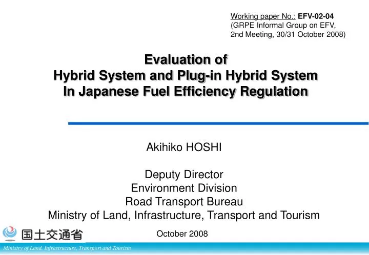
Working paper No.: EFV-02-04 (GRPE Informal Group on EFV, 2nd Meeting, 30/31 October 2008). Akihiko HOSHI Deputy Director Environment Division Road Transport Bureau Ministry of Land, Infrastructure, Transport and Tourism. Evaluation of Hybrid System and Plug-in Hybrid System

E N D
Working paper No.:EFV-02-04 (GRPE Informal Group on EFV, 2nd Meeting, 30/31 October 2008) Akihiko HOSHI Deputy Director Environment Division Road Transport Bureau Ministry of Land, Infrastructure, Transport and Tourism Evaluation of Hybrid System and Plug-in Hybrid System In Japanese Fuel Efficiency Regulation October 2008
Agenda • Top Runner Approach for FE regulation • Fuel Efficiency regulation for HDVs・Simulation Test Method・for HD HEV Test • Fuel Efficiency Regulation for LDVs・Conventional Test Method・for LD HEV Test・Challenge for PHEV Evaluation • IPT Bus : PHEV for HDVs
Maximum improvement: “Top runner approach” ○ By target year, average fuel consumption must be higher than the best fuel efficiency in the base year. ○ Standard should be high but reachable because target values are already achieved by actual vehicles in the base year. ○ Particular types of cars such as HEVs and MT mounted cars are excluded from top runner +α:positive factors -β:negative factors Target Standard Value in Target Year Top-Runner now vehicles future Average now Positive Factors: Technological Improvement Negative Factors: Exhaust Emission Regulations, etc. (trade-off relation with fuel economy) vehicles now Base Year Target Year Year
“Top runner approach”: Positive factor (+α) • Conventional fuel efficiency improvement technologies (2 – 4 % in total) • Engine compression ratio increase, Friction reduction, Weight reduction, • Reduction of vehicle travel resistance, Low rolling resistance tires • Optimizing overall control of engine • Engine improvement [Gasoline engine] • 4 valves (1%), 2 valves and 2 ignitions (2%), Variable valve system (1 – 7 %) • Direct-injection stoichiometric engine (2%), Direct-injection lean-burn engine (10%) • Variable cylinder (7%), Miller cycle (10%) • High volume EGR (2%), Roller cam follower (1%), Offset crank (2%), Variable compression ratio (10%) • Engine improvement [Diesel engine] • 4 valves (1%) , Electronically controlled fuel injection device (1.5%) , Common rail (2.5%), Direct-injection diesel engine (8%), High pressure injection (1%), Supercharger and supercharger efficiency improvement (2 – 2.5%), Intercooler (1%), EGR (0.5 – 1%), Roller cam follower (1.5%), Offset crank (2%) • Auxiliary equipment • Electric power steering (2%), Charge control (0.5%) • Driving system improvement • Idle-neutral control (1%), AT with more gears (1 – 4%), Switch to CVT (7%), Switch to automated MT (AMT/DCT) (9%), Switch to MT (9%) • Introduction of fuel-efficient vehicles • Hybrid vehicles (15 – 70%), Diesel vehicles (20%) , Idling stop vehicles (4 – 7%)
“Top runner approach”: Negative factor (-β) • Exhaust emission regulations (▲3 to ▲7.5% in total) • Caused by technologies used on diesel vehicles and direct-injection lean-burn vehicles in response to the 2009 exhaust emission regulations. • Technologies considered were engine body improvement (NOx reduction by improving EGR, PM reduction by high pressure injection, etc.) and aftertreatment devices such as NOx occlusion reduction catalyst and continuous regeneration type DPF, etc. • Safety regulations (▲0.1 to ▲1.4% in total) • Caused by increased weight and travel resistance as a result of measures against/for offset crash, pedestrian protection, ISO-FIX, etc. • Noise regulations(▲0.1% in total)
Maximum improvement: “Top runner approach” Current Fuel Economy Performance and Level of 2015 Target Standard Values * Example (passenger vehicle:4 weight categories between 971kg and 1420kg) Hybrid Vehicles (excluded form Top-Runner) 2015 New Target Standard Values 2004 Average Fuel Economy * Fuel economy values on this table are measured by JC08 mode.
Fair Competition: “Segmentation by vehicle weight” ○ Segmentation by weight so that competition will become fair in each category Promoting introduction of advanced power-train and vehicles technologies by classifying vehicles into different categories by weight, transmission, fuel, and vehicle type. In the case of a singe standard value - Company A sells mostly compact cars that are above the standard value, so no improvement is necessary. - Company B sells mostly larger vehicles that are below the standard value, so most car need improvement. - Meeting the standard is possible just by increasing the sales of compact cars In the case of a standard value for each category - Both Company A and B must improve the fuel efficiency of cars that are below the standard - Both companies cannot meet the standard by change of model mix and therefore, introduction of advanced technologies is necessary for all the weight class. FE (km/l) Company A Company B Single standard value Standard value for each weight category
Fair Competition: Segmentation by Vehicle Structures (Only for N1) • For N1 vehicles, segments are defined by “several other features” in addition to “vehicles weight”, taking into consideration: • Market of each vehicle type • Applied technology for each vehicle type • Specification/Vehicle structure of each vehicle type
Agenda • Top Runner Approach • Fuel Efficiency regulation for HDVs・Simulation Test under JE05・HD HEV Test • Fuel Efficiency Regulation for LDVs・Conventional Test Method・for LD HEV Test・Challenge for PHEV Evaluation • IPT Bus : PHEV for HDVs
Japanese test mode for HDVs(JE05) Combination of Urban Driving Mode(JE05) and Inter-urban Driving Mode Conversion to Histories of Engine Speed and Engine Torque Urban Driving Mode = JE05 Mode (Emission Test Mode) Engine speed Time (s) Engine torque • Stand-alone Engine Measurement Method • Including Transient Operating Points Time (s) Interurban Driving Mode: 80km/h Constant Speed Mode with Road Gradient
Japanese test mode for HDVs(JE05) Actual Engine Test of Fuel Efficiency by JE05 Mode is NOT feasible and effective. Stand-alone engine test of fuel efficiency by JE05 mode may require a large number of different engine types. The manufacturers spend large resources (time, labor and money) for constructing the testing facility and performing measurements. Evaluation of Fuel Efficiency by Simulation Method
Characteristics of Simulation Method • Using real vehicle and engine specifications Real Fuel consumption map Engine parameters Torque (Nm) Drive train parameters Engine speed (rpm) • The method is an extension way of the emission test. • Low cost and Hi test efficiency • Problems of reproducibility of driving resistance
Simulation Method Phase of conversion Urban driving mode = Driving mode Interurban driving mode Speed vs. time Conversion program •Determine gear-shift positions. •Calculate engine speed and torque. Vehicle specifications Engine speed / torque vs. time Fuel efficiency map Engine Operating Mode Phase of calculation of fuel efficiency Engine torque Torque (Nm) Computing Engine speed Time (s) Engine speed (rpm) Fuel consumption = *Before simulation, perform operation tests to create a fuel efficiency map Fuel efficiency Source: Japan Automobile Research Institute: Survey Report on Evaluation Methods for Heavy Vehicles, March 2003
Simulation Method Flowchart and Equation Engine Operating Mode Eu: Fuel Efficiency Urban Driving Mode JE05 mode E: Fuel Efficiency Combined Interurban Driving Mode 80km/h constant speed mode with gradient Engine Operating Mode Eh: Fuel Efficiency E=1 / (au / Eu + ah / Eh) E: Heavy vehicle mode fuel efficiency (km/L) Eu: Urban driving mode fuel efficiency (km/L) Eh: Interurban driving mode fuel efficiency (km/L) au: Proportion of urban driving mode ah: Proportion of interurban driving mode
HILS Test Method RESS Inverter Engine M/G E/D Measurement of Exhaust Emission •Fuel Efficiency Test ⇒ desired simple method: Simulation Method • Emission Test ⇒ desireddynamo test with only engine: without electric system •System Bench Method for HEV • Structurally-complexsystem • Need multiple E/D for 4-wheel drive vehicles System Bench Method Hardware-In-the-Loop Simulator (HILS) Test Method was developed
HILS Test Method Driver model Hybrid ECU RESS 100 80 Speed (km/h) 60 40 20 0 0 500 1000 1500 2000 Time (sec) Motor model Torque Inverter Battery model Engine speed HILS (Hardware In the Loop Simulator) Chassis Base Vehicle Model HEV (Hybrid Electric Vehicle) imput Vehicle Parameters ・Gear Ratio, eff. ・Eng. spec ・Vehicle spec etc. Engine model Run JE05 Virtual JE05 Running on CPU Get E/G rpm, E/G Torque Exhaust Emission Fuel Consumption E/D Engine Fuel Consumption Ratio Measurement of Exhaust Emission
Test Procedure for Hybrid HDVs Engine torque Engine speed エンジン燃費マップ Time (s) 1st Step Urban Driving Mode Interurban Driving Mode HILS Simulated driving by HILS Program to determine Engine Torque & Engine Speed Vehicle Specification Vehicle weight, Driving Resistance, Full load engine torque, Motor characteristics, Battery characteristics, etc. Input Connect Hybrid ECU(Real) 2nd Step Engine Operating Mode Input Fuel consumption = *Before simulation, perform operation tests to create a fuel efficiency map 2nd step is same as Simulation Method Fuel efficiency
HILS System Main parameters HEV model - Engine (Torque map) - MG (Torque map, Electric-power consumption map) - RESS (Internal resistance, Open-circuit voltage) Engine TM - Vehicle mass MG - Inertia - Transmission efficiency Capacitor Inverter - Gear ratio Simulation results 100 80 60 rpm Vehicle Speed (km/h) 40 sec 20 Torque 0 2000 0 500 1000 1500 sec Time (sec) Calculated fuel economy with F.C. map or Measure exhaust emissions with an engine unit Driver model Acceleration & Braking Digital signal processor Actual ECUs Interface 24V Power Supply Reference vehicle speed (JE05 driving cycle)
Agenda • Top Runner Approach • Fuel Efficiency Standard for HDVs・Simulation Test Method・for HD HEV Test • Fuel Efficiency Standard for LDVs・Conventional Test Method・for LD HEV Test・Challenge for PHEV Evaluation • IPT Bus : PHEV for HDVs
Current Test Procedures for LD Vehicle • Vehicle’s driving wheels placed on virtual road surface (rollers). • Exhaust emission and fuel economy measured when operating vehicle in fixed pattern.
Operation Mode Distance traveled:8.172km Average speed:24.4km/h Maximum speed:81.6km/h Average 22.7km/h 【Japan】 Average31.5km/h Average 77.7km/h 【 US】 Average33.6km/h Tests corresponding to traffic conditions of the respective areas and operation modes are conducted. 【Europe】
Test procedures for HEV Emission weight [g/km] 0 ΔSOC (Current balance) [Ah] Correction of current balance The current balance is corrected to zero based on relational expression with ΔSOC, considering effects by battery’s state of charge (SOC). (1) Exhaust emission measurement [Technical Standard (Attachment 42)] ①Mode test is conducted several times. Relation between current balance (ΔSOC) and exhaust emission weight are obtained. ②When statistical significance can be recognized for each exhaust emission component, exhaust emission weight of the prescribed tests shall be corrected to an exhaust emission weight corresponding to a current balance of zero, based on the inclination of the linear regression formula (correction factor). ③ When there is no statistical significance, corrections do not need to be made. (2) Fuel consumption measurement [TRIAS (5-9-2007)] ①Fuel consumption shall be calculated by carbon balance method using exhaust emission value corrected to a current balance of zero, similar to exhaust emission.
From vehicle with internal combustion engine to HEV, Plug-in HEV HEV Vehicle with internal combustion engine Reduces of petroleum energy consumption GAS GAS Plug-in HEV Replaces petroleum energy with electricity
Characteristics of Plug-in Vehicles 2nd test cycle 4th test cycle 1st test cycle 3rd test cycle ΔSOC= - ΔSOC= - ΔSOC= 0 ΔSOC= 0 100 All Electric Range (AER) type control 80 Blended type control Normal hybrid vehicles 60 Operation of PHEV vehicles change significantly after reaching A km Battery’s state of charge SOC (%) Charge Depleting (CD) mode 40 Charge Sustaining (CS) mode 20 + A’ A 0 Distance (km) Plug-in range (Charge Depleting Range) Charge Depleting (CD) mode: Vehicle is operated by consuming electric energy supplied from external source ) (while reducing battery’s state of charge (SOC)) Charge Sustaining (CS) mode: By fossil combustion power(Engine + regenerated electric energy), operation of the vehicle is controlled so the SOC value remains constant.
Challenges in evaluation of Plug-in HVs 1. Definition of Plug-in range (CD range) • Plug-in range(CD range) does not always show the total work of charged electric power( How can we define capacity of electricity?). - How can we estimate the changing point (A or A’) from test result? 2. Combination of two different performances of CD mode/CS mode) • How can we incorporate utility factor in the process of combination of two different performance of ? • How can we accommodate further and rapid improvement of Plug-in performance in the near future (mainly achieved by new technology on battery power intensity or cost down)? 3. Consumer Information • How can we inform consumers of the multi-layered performance of Plug-in HV without confusion? • The actual performance differs depending on ways of use.
Agenda • Top Runner Approach • Fuel Efficiency Standard for HD Vehicle・Simulation Test Method・for HD HEV Test • Fuel Efficiency Standard for LD Vehicle・Conventional Test Method・for LD HEV Test・Challenge for PHEV Evaluation • IPT Bus : PHEV for HD Vehicle
IPT Hybrid Bus: “Plug-less” Plug-in for HD Vehicle Lithium Ion Battery Unit Power Unit
IPT Hybrid Bus Battery Air Conditioner Diesel Engine Inverter Up & Down (180mm – 50mm) Motor IPT Secondary Coil Power Supply IPT Primary Coil IPT Unit On Board Secondary Coil Big Power Quick Charge Concrete-covered Primary Coil
Driving Demonstration Test 3.実証試験概要 【走行路】 Haneda Airport Shuttle Bus Depot 8.8km / RT by HV drive 3.1km / lap by EV drive Charge Station 第一ターミナル 写真 国際線ターミナル 写真
Vehicle Energy Source Shift Now Internal Combustion Engine Vehicle Gasoline Diesel Etc. Need more Power Density Energy Density for Battery. Near Future PHEV IPT PHEV is EV with On-board Re-charger Far Future Full Electric Vehicle
Right Vehicle to Right Place v v t t HWY Driving Mode Diesel Intercity Suburbs PHEV Distance short long HEV Urban area Delivery City
Thank you all for listening so attentively For further questions: Akihiko HOSHI Environment Division Road Transport Bureau Ministry of Land, Infrastructure, Transport and Tourism E-mail: hoshi-a2rd@mlit.go.jp Tel: +81 3 5253 8604