Download
1 / 18
180 likes | 318 Views
Rapid Prototyping of FPGA based Floating Point DSP Systems. C.H. Ho Department of Computer Science and Engineering The Chinese University of Hong Kong. 30JUN2002. Overview. Introduction Objective Float Design Flow Floating Point Number Representation Float Class Optimization

E N D
Rapid Prototyping of FPGA based Floating Point DSP Systems C.H. Ho Department of Computer Science and Engineering The Chinese University of Hong Kong 30JUN2002
Overview • Introduction • Objective • Float Design Flow • Floating Point Number Representation • Float Class • Optimization • Digital Sine-Cosine Generator • Results • Conclusion
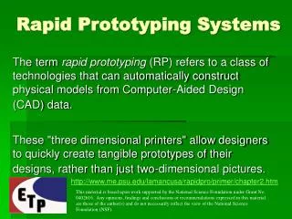
Introduction • FPGA based DSP systems prototyping methodology • Using standard programming language for simulation and verification • Using floating point arithmetic on simulation • Using fixed point operation on implementing hardware • FPGA systems could adapt Floating Point arithmetic • Less overhead in developing DSP systems • FPGA density has improved for using floating point operation • Float – A tools for porting floating point algorithm into hardware • Simulation/Optimization/Implementation can be completed using a single description • Optimize the floating point operation to balance the quantization error and the circuit size • Translate of a high level algorithmic description to an FPGA implementation (under development)
Objective • The tools have the following features • Designer need not have expertise in the implementation of floating point arithmetic • The size of exponent and fraction of the floating point number can be different for each signal • The optimizer uses a user-specified set of input vectors and a cost function which takes into account the tradeoff between quantization error and the size of circuit • Reduced the design time • Simulation is done in high level • Hardware implementation is correct by automatic construction
Float Design Flow • Algorithm is described in Perl Language using the class Float • Cost function suggests the circuit size and quantization error required • Optimizer will minimizes the cost function by varying the precision of Float object • Simulate the algorithm by executing the program • VHDL code produced by compiler
Floating Point Number Representation • Based on the IEEE 754 Floating Point Number Format • e – biased exponent • f – fraction • ebits – size of exponent • bias = 2ebits-1 –1 • Numbers = 1.f x 2(e-bias) • IEEE double precision is used as reference signal for computation of quantization error
Float Class • Simulation of arbitrary precision floating point arithmetic • Core method • add()/multiply() • Return a new Float object representing the sum/product of the argument • Calculate the IEEE 754 double precision as a reference value for computing quantization error • Store the maximum and minimum range of this value for finding minimum exponent • setExponentSize()/setFractionSize() • Adjust the size of the floating point number • getValue()/setValue() • Retrieve/write the value represented by Float object • getQERR() • Return the quantization error between the arbitrary size floating point number and IEEE double precision reference value
Optimization • Two factors: Quantization Error/Circuit Size • Quantization Error (QERR), in decibels • Area of the floating point adder, in Virtex slices • Area of the floating point multiplier, in Virtex slices • Cost Function (a and b are non-negative weightings):
Optimization • Uses Nelder-Mead method to minimize the cost function • Designer can adjust a, b to weight the relative importance of area and QERR • Optimization procedure • Change the precision of Float variable • Simulation the algorithm function at the specified precision • Compare the result with the reference result and compute the cost function • Repeat until the optimization terminates
Digital Sine-Cosine Generator • Let s1 and s2 denote the two outputs of a digital sine-cosine generator • We will use cos(q) = 0.9 in this paper
Digital Sine-Cosine Generator • $cos_theta = new Float(23, 8, 0.9); • $cos_theta_p1 = new Float(23, 8, 1.9); • $cos_theta_m1 = new Float(23, 8, -0.1); • $s1[0] = new Float(23, 8, 0); • $s2[0] = new Float(23, 8, 1); • for ($i = 0 ; $i < 50 ; $i ++) { • $s1[i+1] = $s1[$i] * $cos_theta + • $s2[$i] * $cos_theta_p1; • $s2[i+1] = $s1[$i] * $cos_theta_m1 + • $s2[$i] * $cos_theta; • }
Digital Sine-Cosine Generator • This algorithm can be passed to different component for processing • Simulation • By executing the program, the correctness of the algorithm can be verified • Optimization • Determine the suitable precision format for each of the five Float objects in the algorithm function • Implementation • Parsing the inner loop to produce an expression tree • Generating the VHDL for implementation of reconfigurable computing platform
Results • Different Configuration of Floating Point operator Implemented
Results • Simulation of Algorithm
Results • Quantization Error
Results • Optimization Result
Conclusions • The Float Environment • Enable designers to concentrate on higher level algorithmic issue • Increasing the productivity • The digital sine-cosine generator was implemented • Using Float Environment • Simulation and Optimization involved • Achieve 2% - 5% reduction in area
Thank You Q & A