Download
1 / 52
670 likes | 1.11k Views
Physical and Logical Topologies. Chapter 5. Four standard physical topologies. Bus Star Ring Hybrid. Bus Topology. Single cable connecting all computers Coaxial cable Easy to set up. Bus topology network.

E N D
Physical and Logical Topologies Chapter 5
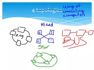
Four standard physical topologies • Bus • Star • Ring • Hybrid
Bus Topology • Single cable connecting all computers • Coaxial cable • Easy to set up
Bus topology network • Signal is heard by all computers, but only the destination computer accepts the data • Passive technology--no active electronics to amplify or regenerate the signal 02608c133456 02608c133456
Terminator Bus topology network • Only one computer at a time can send data • Data collisions occurs if two computers attempt to send data at the same time • Network must beterminated at both ends to prevent signal bounce-back
Advantages of a Bus • Easy to set up • Inexpensive • Easy to add new users • Repeaters can be added to amplify signal
Disadvantages of a Bus • Data collisions may result in slower network traffic • Each connection weakens the electrical signal • Can be hard to troubleshoot • An unplugged cableis not terminated and will take down the network
Ring network • Each device is connected to the next device in the network • Data is passed from one device to the next • Data flows around the ring in one direction
Ring network Sending Computer • A token is passed around the ring • To send data, a computer intercepts the token • Packet of data is attached to the token and addressed to a specific computer • When data is received, message is sent to sending computer and token is placed back on the network Data DestinationComputer Data
Advantages of a Ring • Avoids data collision • Equal access by all computers on the network • Each station acts as a repeater • Regenerates the signal
Disadvantages of a Ring • Additional cost of network adapters and software • Entire network can be affected by a single break in the cable or failure of one computer • As more computers are added to network, response time slows • It is more difficult to troubleshoot a ring network
Star network • Each computer is connected to a central hub • Active hubs—amplify or regenerate signal • Passive hubs—pass signal, no amplification or regeneration Hub
Star network • All data is sent to the hub. • Broadcast star--hub sends data out to all attached devices (passive or active hubs) • Switched star--hub sends data to specific device Hub
Advantages of a Star • A break or unplugged cable takes down only the unplugged computer • Easy to add new computer to network • Hub provides centralized location for diagnosing problems
Disadvantages of a Star • If hub is down, entire network is down • Additional cost for hub and cabling • If passive or active hubs are used, data collisions can occur slowing network traffic
Hybrid Networks • Star-bus • Star-ring
Star-ring network • Computers are attached to a hub (MSAU) but within the hub, a ring is implemented to pass data Hub (MSAU) showing the internal ring and clockwise token path
Star-bus network • Computers are attached to a hub (star). Hubs are attached to other hubs using bus topology. Hub Hub Hub
Enterprise-wide Topologies • Expand on the simple star and star-bus network • Connects hubs, switches, and routers on a network • Fiber-optic cable often used as backbone of enterprise-wide network • Many different ways to implement depending upon needs of organization
Enterprise-wide Topologies • Simplest implementation—series of hubs connect to each other • Creates a single collision domain • All devices on the network have to look at all packets • Hubs to Bridges/Switches • Segments the network • Controls flow of traffic • Routers—create subnetworks
Mesh Network • Provides redundant physical links between network devices • Used in small installations or where it is essential that there always be a path to critical devices • Very fault tolerant • Difficult and expensive to install and reconfigure
True mesh–Each device is connected to every other device Hybrid mesh–Redundant paths are created to critical devices Mesh Network
WAN Topology • WAN—Wide Area Network • Connects geographically distinct locations • Topologies • Peer-to-Peer (Bus) • Ring • Star • Mesh • Tiered
Logical Topologies • The way data will be transmitted between nodes • Most popular logical topologies is: • Ethernet • Other logical topologies include: • Token Ring • FDDI • ATM • LocalTalk
Switching • Technique that determines how connections are made and how data is moved • 3 types of switching • Circuit switching • Message switching • Packet switching
Circuit Switching • Connects sender and receiver by a single physical path for the duration for the conversation • Telephone call is an example of circuit switching • Route selected from sender to receiver varies with each connection but once the connection is made the path stays the same
Advantages of Circuit Switching • Guaranteed data rate • Once circuit is established there are no delays waiting for an available channel • Can be used for time-critical transmission such as audio and video
Message Switching • Messages are stored and forwarded from one intermediate device to another until the message reaches the destination • E-mail messages are an example of message switching • The message is sent from server to server • Sometimes referred to as “store-and-forward”
Message Switching Advantages • Provides effective traffic management • Priority can be assigned to messages so that you can assure that high priority messages are handled promptly • Reduces network traffic • Message can be stored at intermediate devices until a communications channel is available • Provides asynchronous communications across time zones
Packet Switching • Messages are broken into packets • Each packet contains header information including source, destination, sequence number etc. • Individual packets may not follow the same path from the sender to the receiver • The Internet is an example of a packet-switched WAN
Advantages of Packet Switching • If a particular path goes down during transmission, packets can be rerouted • Better use of bandwidth because packets can be sent via different routes
Ethernet • Most popular architecture in use today • Bus, star, or star-bus based technology • Uses baseband signaling • Uses CSMA/CD access method • 10Mbps or 100Mbps transfer rate • Higher rates are now possible • Cable: Thinnet, Thicknet, UTP/STP, Fiber
CSMA/CD • Carrier sense multiple access with collision detection media access method • Contention-based system • Only one workstation can use network at a time • When a collision is detected, workstations wait a random amount of time and retransmit packet • More nodes on the network—the more collisions • Users complain of slow network response
Ethernet Networks • 10Base2 (Thinnet) • 10Base5 (Thicknet) • 10BaseT (Twisted-pair) • 10BaseF (Fiber) • 100BaseT (twisted-pair) • 100BaseFX (Fiber) • Gigabit Ethernet (Fiber or twisted-pair) 10Mbps bandwidth 100Mbps bandwidth 1000Mbps bandwidth
10Base2 Ethernet (Thinnet) • 10Mbps transmission speed; baseband • Maximum segment length--185 meters • Maximum segments--5 • Maximum repeaters--4 • Repeater--device that regenerates network signal to extend the distance signal can travel • Maximum segments with nodes--3 • Maximum nodes per segment--30 • Maximum overall length with repeaters--925 meters
10Base2 Ethernet • Specification is 50-ohm RG-58A/U or RG-58C/U coaxial cable • TV cable is RG-59 • Uses BNC connectors • Transceiver is built into NIC cards--no separate vampire tap transceiver • Connected to NIC by BNC T connector • Terminator must be installed at both ends of network
10Base5 Ethernet (Thicknet) • 10Mbps transmission speed; baseband • Maximum segment length--500 meters • Minimum distance between taps--2.5 meters • Maximum number of taps/segment--100 • Maximum number of segments--5 • Maximum number of repeaters--4 • Maximum number of segments with nodes--3
10Base5 Ethernet • Maximum 300 nodes • Maximum overall length with repeaters--2.5 kilometers (2500 meters) • Maximum AUI cable length--50 meters • Distance from transceiver (vampire tap) to the NIC)
10Base2 & 10Base5 Rule Repeater 2 • The 5-4-3 rule; 5 segments, 4 repeaters, and 3 populated segments Repeater 1 Trunk Segment 2 Trunk Segment 3 Repeater 3 Trunk Segment 1 Repeater 4 Trunk Segment 4 Trunk Segment 5
10BaseT Ethernet (Twisted-Pair) • 10Mbps transmission; baseband • Physically wired as a star • each device connected directly to a hub • hub acts a repeater • Cable: Category 3, 4, or 5 UTP • Maximum segments--1024
10BaseT Ethernet • Maximum segment length--100 meters • Maximum nodes per segment--2 • Maximum nodes per network--1024 • Maximum hubs in a chain—4 • RJ-45 connectors
100BaseT Ethernet (Fast Ethernet) • 100BaseTX • Uses 2 pairs cable • Category 5 UTP, Cat 5E or higher • 100BaseT4 • Uses 4 pairs cable • categories 3, 4, & 5 twisted pair
100BaseT Ethernet • 100Mbps • Specification for maximum segment length, # of segments, #of nodes per segment, etc. are the same as 10BaseT
10BaseF and 100BaseFX • 10Mbps or 100Mbps throughput • Cable: Fiber—multimode • Maximum segment length • 10BaseF—1000-2000meters (1-2 kilometers) • 100BaseF—400meters • Star-bus topology
Gigabit Ethernet • Typically used for backbone • Hub to hub; hub to switch; hub to router • Fiber-optic cable (typically) • Can be implemented for UTP • Speeds in excess of 1000Mbps (1Gbps)
Token Ring • Robust, reliable network architecture developed by IBM • Addressed by 802.5 standard • Physically may look like a star but logically works like a ring • Star-ring topology • Workstations connect to a MAU, MSAU or SMAU • MSAU--MultiStation Access Unit
Token Ring Specifications • Bandwidth--4Mbps or 16Mbps • All cards on the network must be configured the same • 100Mbps token ring is available but not widely implemented • Called HSTR (High-Speed Token Ring) • Cable--UTP, STP, fiber • Maximum MSAU--33 • Maximum nodes per MSAU--8 (IBM) • Maximum nodes—255 (STP) 72 (UTP)
Adding hubs while maintaining the logical ring Ring out Ring in Ring out Ring in Ring out Ring in Ring out Ring in Ring in Ring out
FDDI(Fiber Distributed Data Interface) • Networking standard originally specified by ANSI in the 1980s and later refined by ISO • Uses a dual fiber-optic ring to transmit data at speeds of 100 Mbps • Dual counter-rotating rings provide fault tolerance • Used to connect LANs located in multiple buildings, e.g., a large campus
FDDI (Fiber Distributed Data Interface) • Cable lengths can extend 100 km (62 miles) with repeaters every 2 km • Access to network is controlled using a token passing scheme • Can attach up to 500 nodes • Computers can be attached to only the primary ring or to both rings • Computers attached to both rings are called Class A stations (dual-attached stations) • Computers attached to only the primary ring are called Class B stations (single-attached stations)