Download
1 / 11
110 likes | 112 Views
the connecting rod is the mediator member between the piston and the Connecting Rod. Its primary function is to transmit the push and pull from the piston pin to the crank pin and thus convert the reciprocating motion of the piston into rotary motion of the crank. For piston pin there will be tiny end is fix, it will used mostly to press fit into the connecting rod but it can swivel in the piston, a floating wrist pin design. Presently connecting rod is manufacturing by using the material Carbon steel. In this project, connecting rod is designed using Aluminum alloys 7475 and 6061. The aim of this project is to design the connecting rod for 150cc engine motorbike by using Design formulas for the above materials. By using catia software we can draw the 3Dmodel of the connecting rod as per the parameters. All the required data is collected from design data books, internet and journals. Vytla Jayaprakash | Dr. Alok Kumar Rohit | Ch. Srinivas "Non Linear Analysis of Diesel Engine Connecting Rod" Published in International Journal of Trend in Scientific Research and Development (ijtsrd), ISSN: 2456-6470, Volume-2 | Issue-6 , October 2018, URL: https://www.ijtsrd.com/papers/ijtsrd18485.pdf Paper URL: http://www.ijtsrd.com/engineering/automotive-engineering/18485/non-linear-analysis-of-diesel-engine-connecting-rod/vytla-jayaprakash<br>

E N D
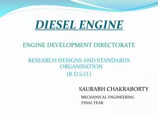
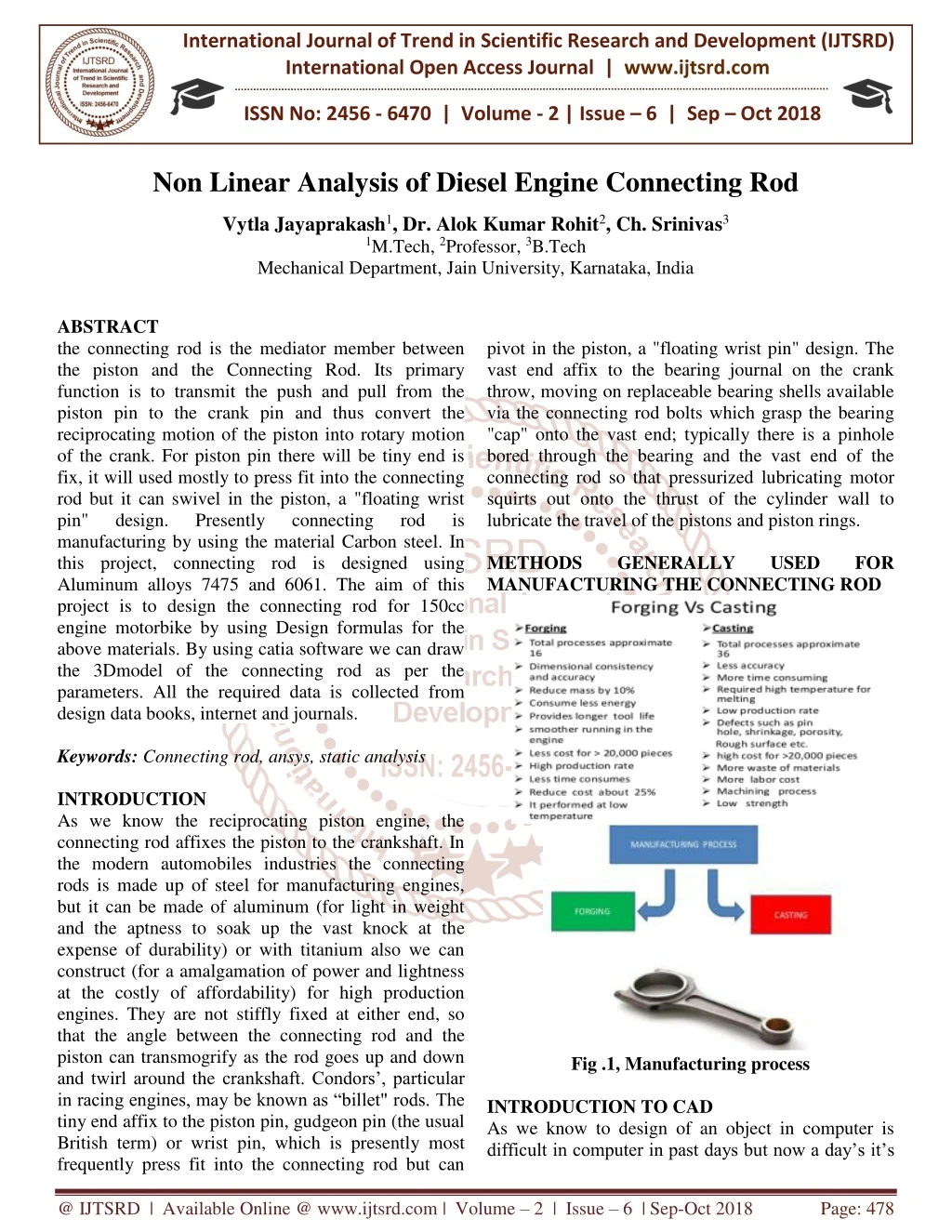
International Journal of Trend in Scientific Research and Development (IJTSRD) International Open Access Journal | www.ijtsrd.com ISSN No: 2456 - 6470 | Volume - 2 | Issue – 6 | Sep – Oct 2018 Non Linear Analysis of Diesel Engine Connecting Rod Vytla Jayaprakash1, Dr. Alok Kumar Rohit2, Ch. Srinivas3 1M.Tech, 2Professor, 3B.Tech Mechanical Department, Jain University, Karnataka, India ABSTRACT the connecting rod is the mediator member between the piston and the Connecting Rod. Its primary function is to transmit the push and pull from the piston pin to the crank pin and thus convert the reciprocating motion of the piston into rotary motion of the crank. For piston pin there will be tiny end is fix, it will used mostly to press fit into the connecting rod but it can swivel in the piston, a "floating wrist pin" design. Presently connecting rod manufacturing by using the material Carbon steel. In this project, connecting rod is designed using Aluminum alloys 7475 and 6061. The aim of this project is to design the connecting rod for 150cc engine motorbike by using Design formulas for the above materials. By using catia software we can draw the 3Dmodel of the connecting rod as per the parameters. All the required data is collected from design data books, internet and journals. Keywords:Connecting rod, ansys, static analysis INTRODUCTION As we know the reciprocating piston engine, the connecting rod affixes the piston to the crankshaft. In the modern automobiles industries the connecting rods is made up of steel for manufacturing engines, but it can be made of aluminum (for light in weight and the aptness to soak up the vast knock at the expense of durability) or with titanium also we can construct (for a amalgamation of power and lightness at the costly of affordability) for high production engines. They are not stiffly fixed at either end, so that the angle between the connecting rod and the piston can transmogrify as the rod goes up and down and twirl around the crankshaft. Condors’, particular in racing engines, may be known as “billet" rods. The tiny end affix to the piston pin, gudgeon pin (the usual British term) or wrist pin, which is presently most frequently press fit into the connecting rod but can pivot in the piston, a "floating wrist pin" design. The vast end affix to the bearing journal on the crank throw, moving on replaceable bearing shells available via the connecting rod bolts which grasp the bearing "cap" onto the vast end; typically there is a pinhole bored through the bearing and the vast end of the connecting rod so that pressurized lubricating motor squirts out onto the thrust of the cylinder wall to lubricate the travel of the pistons and piston rings. METHODS GENERALLY MANUFACTURING THE CONNECTING ROD is USED FOR Fig .1, Manufacturing process INTRODUCTION TO CAD As we know to design of an object in computer is difficult in computer in past days but now a day’s it’s @ IJTSRD | Available Online @ www.ijtsrd.com | Volume – 2 | Issue – 6 | Sep-Oct 2018 Page: 478
International Journal of Trend in Scientific Research and Development (IJTSRD) ISSN: 2456-6470 PROCESS FOR ANSYS ANALYSIS By utilizing the Static analysis we can find out the displacements, stresses, strains and forces in structures or components during the loads conditions that do not leading remarkable inertia and damping effects. Firstly Steady loading conditions are to be assumed. These types of loading that can be applied in a static analysis include the forces and pressures, steady state inertial forces such as gravity velocity imposed (non zero) displacements, temperature (for thermal strain). A static analysis can be either linear or non linear. For your work we are choosing the linear statistic analysis. For Procedure of static analysis it consists 3 main steps they are: ➢Construction of the model ➢Getting the solution. ➢Reviewing the repercussion. so simple firstly we know Computer-aided design (CAD) it is software now a day’s it’s made so easy to draw 2D and 3D diagrams in computers. It’s also called as computer-aided design and drafting (CADD).By the using of Computer Aided Drafting which explains the drafting process in computer. For many of design engineering CADD software is a flagship tool by using this software they shows the elegant designs of the objects as per the requirements. The output of CADD is in the form of print or machining operations. The required output information is also important for CAD such as materials, processes, dimensions, and tolerances, according to specific applications. The design curves and figures in two-dimensional (2D) space and solids surface in three-dimensional (3D) objects are shown in CAD software.. The design of geometric objects for object shapes, in particular, is often called computer-aided geometric design (CAGD). ANSYS – AN OVERVIEW For design and investigation of engineering difficulties or problems we can solve by using the software is called ANSYS software. The ANSYS is finite element analysis software for advanced by ANSYS INC. It is user friendly graphical user interface package. Many no of CAD Programmers have straight interfaces with the ANSYS program through software written by ANSYS.INC or by the CAD vendors. Interpreter for the programs like AutoCAD and Pro/Engineer are accessible from ANSYS.INC. There are following tasks which enable the ANSYS finite element analysis software for engineers to execute the performance on the models. 1.Construct the computer models or send CAD models of structures, products, components or system. 2.Petition the operating loads or other design production state. 3.Examine the physical properties, such as stress levels, temperature disseminate, etc. 4.Optimize a design early in growth action to diminish manufacture prices. 5.Do prototype testing in ambient where it otherwise would be undesirable or impossible. 6.The essential goal of finite element analysis is to investigate how the responds from the elements or models under the certain loading condition Fig.2, 2D MODELOF CONNECTING ROD Fig.3, 3D MODEL OF CONNECTING ROD Fig.4, BIG CAP END @ IJTSRD | Available Online @ www.ijtsrd.com | Volume – 2 | Issue – 6 | Sep-Oct 2018 Page: 479
International Journal of Trend in Scientific Research and Development (IJTSRD) ISSN: 2456-6470 Fig.7, Strain Fig.5, FINAL ASSEMBLY COMPONENT ANALYSIS OF CONNECTING ROD STATIC ANALYSIS Fig.8, Stress MATERIAL – ALUMINIUM ALLOY 6061 Material properties Density: 2.70g/cc Young’s modulus68.9gpa Poisson’s ratio: 0.33 Select engineering data> window will be open in that enter required material properties> MATERIAL – ALUMINIUM ALLOY 7475 Material properties Density: 2.81g/cc Young’s modulus70.3gpa Poisson’s ratio: 0.33 Fig: .9, Deformation Fig.6, Deformation Fig.10, Strain @ IJTSRD | Available Online @ www.ijtsrd.com | Volume – 2 | Issue – 6 | Sep-Oct 2018 Page: 480
International Journal of Trend in Scientific Research and Development (IJTSRD) ISSN: 2456-6470 Right click on Modal>Insert>Displacement>Select faces>apply. Fig.11, Stress Fig.13, Fixed support Right click on Solution>Insert>Deformation>Total>Mode1. Right click on Solution>Insert>Deformation>Total>Mode2…..etc Right click on Solution >Solve. B. MODAL ANALYSIS CARBON STEEL ANSYS> Work bench 14.5>Double click on Modal. Right click on Engineering data>edit>apply material properties>return project>Update project. Material properties Density: 7.89g/cc Young’s modulus: 213 GPa Poisson’s ratio: 0.30 Right click on Geometry>Imported Geometry>browse>click on IGS file>Open. Fig.14, Mode 1 Fig.15, Mode 2 Fig.12, Imported Geometry Right click on Model>Edit>Right click on mesh>sizing>fine>Right click on mesh>generate mesh. Fig.16, Mode 3 @ IJTSRD | Available Online @ www.ijtsrd.com | Volume – 2 | Issue – 6 | Sep-Oct 2018 Page: 481
International Journal of Trend in Scientific Research and Development (IJTSRD) ISSN: 2456-6470 ALUMINIUM ALLOY 7475 Fig.17, Mode 1 Fig.21, Imported model Fig.18, Mode 2 Fig.22, mesh Enter the higher frequencies value (taken from modal analysis) Fig.19, Mode 3 Select displacement → select required area → click on apply → Displacement Select Pressure → select required area and enter the pressure value → click on apply → Pressure Solution –right click-solve-select solution –right click –total deformation Select solution –right click –stress Select solution –right click –strain Select solution –right click –Phase response Select solution –right click –Frequency response C. HARMONIC ANALYSIS MATERIAL – CARBON STEEL Fig.20, Harmonic Analysis @ IJTSRD | Available Online @ www.ijtsrd.com | Volume – 2 | Issue – 6 | Sep-Oct 2018 Page: 482
International Journal of Trend in Scientific Research and Development (IJTSRD) ISSN: 2456-6470 Fig.23, Total Deformation at the frequency Fig.27, Frequency response MATERIAL - ALUMINUM7475 Fig.24, Strain at the frequency Fig.28, total deformation Fig.25, Stress at the frequency Fig.29, strain Fig.26, Phase response Fig.30, stress @ IJTSRD | Available Online @ www.ijtsrd.com | Volume – 2 | Issue – 6 | Sep-Oct 2018 Page: 483
International Journal of Trend in Scientific Research and Development (IJTSRD) ISSN: 2456-6470 Fig.35, total deformation 5sec: Fig.31, phase response Fig.36, total deformation 10sec Fig.32, frequency response TRANSIENT STRUCTURAL MATERIAL - Carbon steel At 1sec: Fig.37, total deformation MATERIAL - ALUMINUM7475 1 sec: Fig33, displacement Fig.38, total deformation 5sec Fig.34, pressure @ IJTSRD | Available Online @ www.ijtsrd.com | Volume – 2 | Issue – 6 | Sep-Oct 2018 Page: 484
International Journal of Trend in Scientific Research and Development (IJTSRD) ISSN: 2456-6470 Graph.2 STRAIN 0.0006 0.0005 0.0004 0.0003 Strain 0.0002 0.0001 STRAIN 0 Fig.39, total deformation 10sec: Graph.3 STRESS (MPa) 50 40 30 Stress (Mpa) 20 STRESS (MPa) 10 0 Fig.40, total deformation Carbon steel Aluminum alloy 7475 Aluminum alloy 6061 RESULT TABLES Table.1 STATIC ANALYSIS Deformati on (mm) Stress (MPa) Strain Table .2 MODAL ANALYSIS Aluminu m alloy7475 Aluminu m alloy6061 Carbon steel Aluminum alloy 7475 Aluminum alloy 6061 Structura l steel 0.0012566 0.00016501 45 0.0038472 0.00050038 34.889 Mode 1 (mm) 144.46 242.1 246.98 0.0039254 0.00051055 34.889 Frequency 1 (Hz) 364.13 350.73 354.23 GRAPHS.1 Mode 2 (mm) DEFORMATION (mm) 147.88 247.79 252.79 0.005 Deformation (mm) 0.004 Frequency 2 (Hz) 554.35 533.68 539 0.003 0.002 DEFORMATIO N (mm) 0.001 Mode 3 (mm) 137.27 229.99 234.63 0 Frequency 3 (Hz) 2225.25 2168.8 2190.4 @ IJTSRD | Available Online @ www.ijtsrd.com | Volume – 2 | Issue – 6 | Sep-Oct 2018 Page: 485
International Journal of Trend in Scientific Research and Development (IJTSRD) ISSN: 2456-6470 Graph.4 Graph.7 DEFORMATION (mm) STRAIN 300 Deformation (mm) 7.00E-05 250 6.00E-05 200 5.00E-05 4.00E-05 Strain 150 3.00E-05 Mode 1 100 2.00E-05 50 1.00E-05 Mode 2 STRAIN 0.00E+00 0 Mode 3 graph.5 Graph.8 STRESS (MPa) Frequency (Hz) 12 2500 10 Frequency (Hz) 2000 8 Frequency 1 (Hz 1500 Stress (Mpa) 6 1000 STRESS (MPa) 4 Frequency 2 (Hz) 500 2 0 Frequency 3 (Hz) 0 Carbon steel Aluminum alloy 7475 Aluminum alloy 6061 HARMONIC ANALYSIS Table.3 Deformati on (mm) Carbon steel 0.0089825 aluminum alloy 7475 aluminum alloy 6061 TRANSIENT ANALYSIS Table.4 for1sec: Deformati on (mm) Stress (MPa) 9.7985 Stress (MPa) Strain Strain 4.6124e-5 Carbon steel 0.0012569 0.00016501 34.857 0.012063 6.1925e-5 4.3415 aluminum alloy 7475 aluminum alloy 6061 0.0038504 0.0005039 34.89 0.011382 5.8427e-5 4.0147 0.0039287 0.00051056 34.89 Graph.6 DEFORMATION (mm) 0.014 Table.5 for 5sec: Deformati On (mm) 0.012 Deformation (mm) Stress (MPa) 0.01 Strain 0.008 0.006 DEFORMATI ON (mm) Carbon steel 0.0013719 0.0001801 38.045 0.004 0.002 aluminum alloy 7475 aluminum alloy 6061 0.0042033 0.00054618 38.083 0 Carbon steel Aluminum alloy 7475 Aluminum alloy 6061 0.0042888 0.00055728 38.083 @ IJTSRD | Available Online @ www.ijtsrd.com | Volume – 2 | Issue – 6 | Sep-Oct 2018 Page: 486
International Journal of Trend in Scientific Research and Development (IJTSRD) ISSN: 2456-6470 Table .6 for 10sec: Deformati on (mm) CONCLUSION In this project we can modeled and designed 3D model of diesel engine connecting rod is by using software catia. Static, Modal, Harmonic and Transient analysis is performed on the connecting rod in ansys for different materials Structural Steel, Aluminum alloy 7475 and 6061. As we notice the plebiscite of structural analysis, for Aluminum alloy 7475 material the deformation and stress values are diminished. By noticing the plebiscite of modal analysis, the deformation values are less for Aluminum alloy. So vibrations will be less when Aluminum 7475 is used. By observing the plebiscite of Harmonic and Transient analysis, the stress values are diminishing for the Aluminum alloy 7475. So it can be concluded that using Aluminum alloy 7475 is better due to less stress values and high strength to weight ratio. REFERENCES 1.Static stress analysis of connecting rod using finite element approach by Abhinav Gautam, K Priya Ajit, IOSR Journal of Mechanical and Civil Engineering (IOSR-JMCE) e-ISSN: 2278-1684,p- ISSN: 2320-334X, Volume 10, Issue 1 (Nov. - Dec. 2013), PP 47-51 2.Dynamic simulation of a connecting rod made of aluminum alloy using finite element analysis approach by Ram Bansal, IOSR Journal of Mechanical and Civil Engineering (IOSR-JMCE) e-ISSN: 2278-1684 Volume 5, Issue 2 (Jan. - Feb. 2013), PP 01-05 3.Analysis and optimization of connecting rod using AlFASiC composites by Kuldeep B, Arun L.R, Mohammed Faheem,ISSN: International Journal of Innovative Research in Science, Engineering and Technology Vol. 2, Issue 6, June 2013 4.Connecting Rod Optimization for Weight and Cost Reduction by Pravardhan S. Shenoy and Ali Fatemi, SAE Technical Paper 2005-01-0987, 2005, doi:10.4271/2005-01-0987. 5.Process capability improvement of an engine connecting rod machining process by GVSS Sharma and P Srinivasa Rao, Journal of Industrial Engineering International doi:10.1186/2251-712X-9-37 Stress (MPa) Strain Carbon steel 0.0014869 0.00019579 41.233 aluminum alloy 7475 aluminum alloy 6061 Graph.9 0.0045558 0.00059194 41.274 0.0046485 0.00060397 41.274 DEFORMATION (mm) 0.005 Deformation (mm) 0.004 DEFORMATI ON (1 Sec) 0.003 0.002 0.001 DEFORMATI ON (5 Sec) 0 DEFORMATI ON (10 Sec) Graph.10 STRAIN 0.0007 0.0006 0.0005 STRAIN(1 Sec) 0.0004 Strain 0.0003 0.0002 STRAIN(5 Sec) 0.0001 0 STRAIN(10 Sec) 2319-8753 , Graph.11 STRESS (MPa) 42 40 38 STRESS (1 SEC) Stress (Mpa) 36 34 STRESS (2 SEC) 32 STRESS (3 SEC) 30 Carbon steel Aluminum alloy 7475 Aluminum alloy 6061 2013, 9:37 @ IJTSRD | Available Online @ www.ijtsrd.com | Volume – 2 | Issue – 6 | Sep-Oct 2018 Page: 487
International Journal of Trend in Scientific Research and Development (IJTSRD) ISSN: 2456-6470 6.Modeling and Analysis of Two Wheeler Connecting Rod by K. Sudershn Kumar, Dr.K. Tirupathi Reddy, International Journal of Modern Engineering Research (IJMER), Vol.2, Issue.5, Sep-Oct. 2012 pp-3367-3371 ISSN: 2249-6645 7.Design Evaluation Connecting Rod Parameters Using FEM by Suraj Pal, Sunil kumar, International Journal of Engineering and Management Research, Vol.-2, Issue-6, December 2012 8.Stress Analysis of I.C.Engine Connecting Rod by FEM and Photo elasticity by Prof. Vivek C. Pathade , Dr. Dilip S. Ingole, IOSR Journal of Mechanical and Civil Engineering (IOSR-JMCE) e-ISSN: 2278-1684 Volume 6, Issue 1 (Mar. - Apr. 2013), PP 117-125 9.Design And Finite Element Analysis Of Aluminium-6351 Connecting Rod by Priyank D. Toliya, Ravi C. Trivedi, Prof. Nikhil J. Chotai, Volume/Issue: Vol.2 - Issue 5 (May - 2013), e- ISSN: 2278-0181 Syed Altaf Hussain, and Optimization of @ IJTSRD | Available Online @ www.ijtsrd.com | Volume – 2 | Issue – 6 | Sep-Oct 2018 Page: 488