Download
1 / 8
80 likes | 94 Views
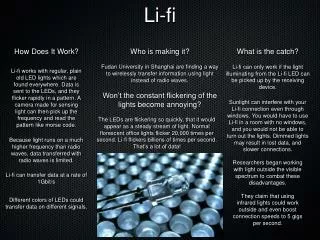
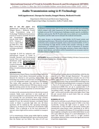
Light Fidelity Li Fi technology is a novel method of wireless communication network based on the use of visible LED lights between the violet 800 THz and red 400 THz to transmit data wirelessly. Li Fi has much broader spectrum compared to conventional methods of wireless communication for data transmission which depends on radio waves. The principle of Li Fi is based on sending data by amplitude modulation of light source in a well defined and consistent way. The concept of Li Fi assures to solve issues like shortage of radio frequency bandwidth and eliminates the drawbacks of Radio communication technologies. Li Fi technology provides better bandwidth, faster transfer speed, efficiency and security as compared with Wi Fi. This paper focuses on working of Li Fi, its applications, features and comparison with existing technologies like Wi Fi etc. P. Valarmathi "Li-Fi Technology in Wireless Data Communication" Published in International Journal of Trend in Scientific Research and Development (ijtsrd), ISSN: 2456-6470, Volume-2 | Issue-5 , August 2018, URL: https://www.ijtsrd.com/papers/ijtsrd18299.pdf Paper URL: http://www.ijtsrd.com/engineering/electronics-and-communication-engineering/18299/li-fi-technology-in-wireless-data-communication/p-valarmathi<br>

E N D
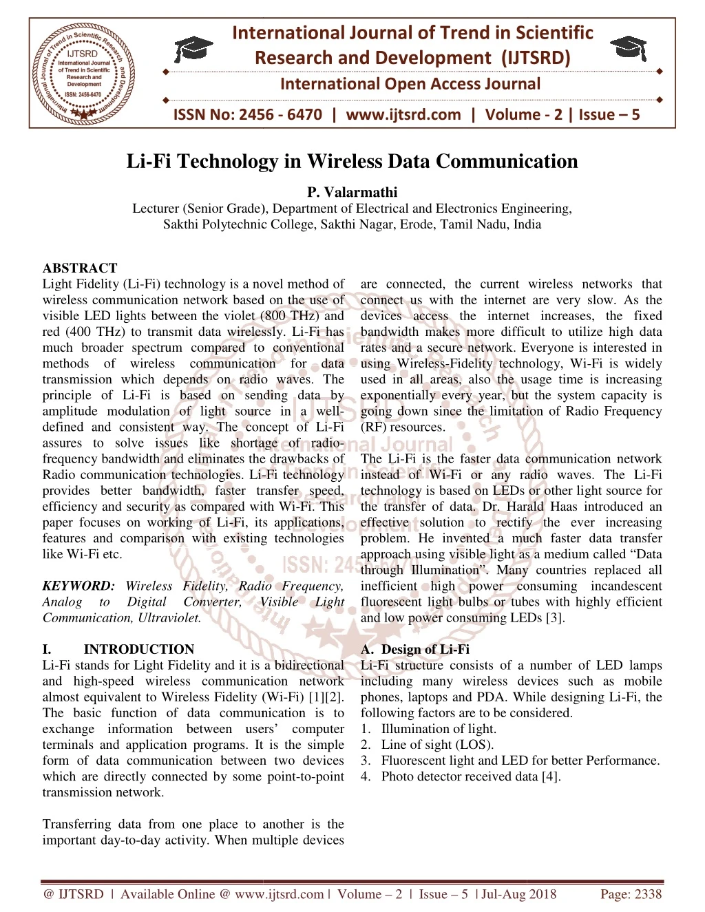
International Research Research and Development (IJTSRD) International Open Access Journal Fi Technology in Wireless Data Communication P. Valarmathi Lecturer (Senior Grade), Department of Electrical and Electronics Engineering, Sakthi Polytechnic College, Sakthi Nagar, Erode, Tamil Nadu, India International Journal of Trend in Scientific Scientific (IJTSRD) International Open Access Journal ISSN No: 2456 ISSN No: 2456 - 6470 | www.ijtsrd.com | Volume 6470 | www.ijtsrd.com | Volume - 2 | Issue – 5 Li-Fi Technology Wireless Data Communication Lecturer (Senior Grade), Department of Electrical and Electronics Engineering, Sakthi Polytechnic College, Sakthi Nagar, Erode, Tamil Lecturer (Senior Grade), Department of Electrical and Electronics Engineering, Nadu, India ABSTRACT Light Fidelity (Li-Fi) technology is a novel method of wireless communication network based on the use of visible LED lights between the violet (800 THz) and red (400 THz) to transmit data wirelessly. much broader spectrum compared to conventional methods of wireless communication for data transmission which depends on radio waves. The principle of Li-Fi is based on sending data by amplitude modulation of light source in a well defined and consistent way. The concept of Li assures to solve issues like shortage of radio frequency bandwidth and eliminates the drawbacks of Radio communication technologies. Li- provides better bandwidth, faster transfer speed, efficiency and security as compared with Wi paper focuses on working of Li-Fi, its applications, features and comparison with existing technologies like Wi-Fi etc. KEYWORD: Wireless Fidelity, Radio Frequency, Analog to Digital Converter, Communication, Ultraviolet. I. INTRODUCTION Li-Fi stands for Light Fidelity and it is a bidirectional and high-speed wireless communication network almost equivalent to Wireless Fidelity (Wi The basic function of data communication is to exchange information between users’ computer terminals and application programs. It is the simple form of data communication between two devices which are directly connected by some point transmission network. Transferring data from one place to another is the important day-to-day activity. When multiple devices are connected, the current wireless networks that connect us with the internet are very slow. As the devices access the internet increases, the fixed bandwidth makes more difficult to utilize high data rates and a secure network. Every using Wireless-Fidelity technology, Wi used in all areas, also the usage time is increasing exponentially every year, but the system capacity is going down since the limitation of Radio Frequency (RF) resources. The Li-Fi is the faster data communication network instead of Wi-Fi or any radio waves. The Li technology is based on LEDs or other light source for the transfer of data. Dr. Harald Haas introduced an effective solution to rectify the ever increasing problem. He invented a much faster data transfer approach using visible light as a medium called “Data through Illumination”. Many countries replaced all inefficient high power consuming incandescent fluorescent light bulbs or tubes with highly efficient and low power consuming LEDs [3]. A.Design of Li-Fi Li-Fi structure consists of a number of LED lamps including many wireless devices such as mobile phones, laptops and PDA. While designing Li following factors are to be considered. 1.Illumination of light. 2.Line of sight (LOS). 3.Fluorescent light and LED for better Performance. 4.Photo detector received data [4]. Photo detector received data [4]. Fi) technology is a novel method of are connected, the current wireless networks that connect us with the internet are very slow. As the devices access the internet increases, the fixed bandwidth makes more difficult to utilize high data rates and a secure network. Everyone is interested in Fidelity technology, Wi-Fi is widely used in all areas, also the usage time is increasing exponentially every year, but the system capacity is going down since the limitation of Radio Frequency wireless communication network based on the use of visible LED lights between the violet (800 THz) and red (400 THz) to transmit data wirelessly. Li-Fi has much broader spectrum compared to conventional methods of wireless communication for data transmission which depends on radio waves. The Fi is based on sending data by amplitude modulation of light source in a well- sistent way. The concept of Li-Fi assures to solve issues like shortage of radio- frequency bandwidth and eliminates the drawbacks of i is the faster data communication network Fi or any radio waves. The Li-Fi technology is based on LEDs or other light source for the transfer of data. Dr. Harald Haas introduced an effective solution to rectify the ever increasing e invented a much faster data transfer approach using visible light as a medium called “Data through Illumination”. Many countries replaced all inefficient high power consuming incandescent fluorescent light bulbs or tubes with highly efficient er consuming LEDs [3]. -Fi technology provides better bandwidth, faster transfer speed, y as compared with Wi-Fi. This Fi, its applications, features and comparison with existing technologies Wireless Fidelity, Radio Frequency, Digital Converter, Analog to Visible Visible Light Light Fi stands for Light Fidelity and it is a bidirectional speed wireless communication network almost equivalent to Wireless Fidelity (Wi-Fi) [1][2]. The basic function of data communication is to exchange information between users’ computer nals and application programs. It is the simple form of data communication between two devices which are directly connected by some point-to-point Fi structure consists of a number of LED lamps including many wireless devices such as mobile phones, laptops and PDA. While designing Li-Fi, the following factors are to be considered. Fluorescent light and LED for better Performance. Transferring data from one place to another is the n multiple devices @ IJTSRD | Available Online @ www.ijtsrd.com @ IJTSRD | Available Online @ www.ijtsrd.com | Volume – 2 | Issue – 5 | Jul-Aug 2018 Aug 2018 Page: 2338
International Journal of Trend in Scientific Research and Development (IJTSRD) ISSN: 2456 International Journal of Trend in Scientific Research and Development (IJTSRD) ISSN: 2456 International Journal of Trend in Scientific Research and Development (IJTSRD) ISSN: 2456-6470 Destination Computer: Receiver Module to Data Interpretation Module to Data Display (GUI). The different components serve the following functions: Data Conversion component: byte format represented as a digital encrypt the data before conversion. Transmitter component: corresponding ON-OFF states for LEDs. Receiver component: It has a photo diode to sense the ON-OFF states of LEDs. It captures the sequence and generates the binary sequence of the receiving signal. Data Interpretation component: into its original format. If encryption was completed, it also performs decryption [9]. The of Li-Fi is shown in figure 2. B.Fundamental Communication Fundamental Block Block Diagram Diagram of of Li Li-Fi Receiver Module to Data Interpretation Module to Data Display (GUI). The different components serve the following Data Conversion component: It converts data into byte format represented as a digital signal. Also, it can encrypt the data before conversion. It produces the OFF states for LEDs. Figure 1: Fundamental block diagram of Li Figure 1: Fundamental block diagram of Li-Fi system It has a photo diode to sense [5] [6] OFF states of LEDs. It captures the sequence and generates the binary sequence of the receiving Figure 1 shows the fundamental block diagram of Li Fi system. There are two sections namely transmitter and receiver. In the transmitter, the data is first converted to binary through an Analog to Digital Converter (ADC) and then it is fed into a LED driver circuit controlled by a signal processor. The LED driver works on the modulation of On-Off Keying [7]. A high illumination LED flickers at high speed and transmits the data through a wireless medium as optical pulses. These optical pulses are converted into an electrical signal by a photo detector on the receiver side, which are amplified by a trans amplifier and then converted into a binary data using comparator. The LED lights will be networked and hence more number of users can access data by using a single LED light or move from one light to another without affecting their access [8]. C.Implementation of Li-Fi The main components of Li-Fi system based on, 1.High brightness LEDs acts as a communication source. 2.Silicon photodiode acts as a receiving element. The data is converted into byte format and then converted into light signals emitted by the transmitter unit. On the receiver side, the light signal is received by the photodiode. The reverse process takes place at the computer destination to recover the data back from the received light. LEDs are engaged as the light sources. The model transmits the signal in digital format by means of direct light modulation. The emitted light is detected by an optical receiver. Source Computer: Data Reading Module to Data Conversion Module to Transmitter Module. diagram of Li- Fi system. There are two sections namely transmitter and receiver. In the transmitter, the data is first converted to binary through an Analog to Digital Converter (ADC) and then it is fed into a LED driver Data Interpretation component: It converts the data into its original format. If encryption was completed, o performs decryption [9]. The Implementation essor. The LED Off Keying [7]. A high illumination LED flickers at high speed and transmits the data through a wireless medium as optical pulses. These optical pulses are converted into etector on the receiver side, which are amplified by a transimpedance amplifier and then converted into a binary data using comparator. The LED lights will be networked and hence more number of users can access data by using Figure 2: Implementation of Li Figure 2: Implementation of Li-Fi [10] one light to another D.Working of Li-Fi A new generation of high illumination LEDs forms the core of Li-Fi technology. The logic followed in Li-Fi technology is very simple. If the LED is ON, a digital 1 is transmitted. If the LED is OFF, a digital 0 is transmitted. These high illumination LEDs can be switched ON and OFF very quickly which gives a great opportunity for the transmission of data through light [11]. The working of Light Fidelity is very simple. There is a light emitter on one side, for example, an LED and a photo detector or light sensor on the other side. The photo detector registers a binary 1 when the LED is ON and a binary 0 if the LED is OFF. a message, flash the LED number of times or use an array of LEDs with few colors if possible, to attain data rates in the range of hundreds of megabits per second. The working of Li- figure 3. A new generation of high illumination LEDs forms Fi technology. The logic followed in s very simple. If the LED is ON, a digital 1 is transmitted. If the LED is OFF, a digital 0 is transmitted. These high illumination LEDs can be switched ON and OFF very quickly which gives a great opportunity for the transmission of data through . The working of Light Fidelity is very simple. There is a light emitter on one side, for example, an LED and a photo detector or light sensor Fi system based on, High brightness LEDs acts as a communication Silicon photodiode acts as a receiving element. nto byte format and then converted into light signals emitted by the transmitter unit. On the receiver side, the light signal is received by the photodiode. The reverse process takes place at the computer destination to recover the data back ved light. LEDs are engaged as the light sources. The model transmits the signal in digital format by means of direct light modulation. The emitted light is detected by an optical receiver. The photo detector registers a binary 1 when the LED is ON and a binary 0 if the LED is OFF. To construct a message, flash the LED number of times or use an array of LEDs with few colors if possible, to attain data rates in the range of hundreds of megabits per Data Reading Module to Data o Transmitter Module. -Fi system is shown in @ IJTSRD | Available Online @ www.ijtsrd.com @ IJTSRD | Available Online @ www.ijtsrd.com | Volume – 2 | Issue – 5 | Jul-Aug 2018 Aug 2018 Page: 2339
International Journal of Trend in Scientific Research and Development (IJTSRD) ISSN: 2456-6470 The loudspeaker is connected to the analog input port of second PC in which the sound is received. The spectrum of this signal received from speaker is plotted using simulation. There are two stages in receiver unit. In first stage, photo detector current converts into voltage level and in second stage, inverting amplifier inverts once to acquire original information [14]. Figure 3: Working of Li-Fi system [12] The data can be encoded by varying the flickering rate of light and the LEDs ON and OFF stages will generate different strings of 1s and 0s. The intensity of light is modulated so quickly that human eye cannot observe, hence it appears constant to humans [13]. II. Components of Li-Fi System A.Transmitter Section It consists of a PC and a Li-Fi transmitter. PC is used to generate a sinusoidal wave signal with particular frequency. This signal is given to the Li-Fi transmitter as input by using a connector coupled to the PC analog output port. The circuit diagram for Li-Fi transmitter is shown in figure 4. The analog signal received from PC, passes through the low power audio amplifier IC LM386, gets amplified. The output of the LM386 is encoded in light form in which the data is transferred at high speed. Figure 5: Li-Fi Receiver Circuit [14] C. Photodiode In Li-Fi technology, a photo detector is on the receiver side, which converts the incident light into electric signals and gives the electric signals to the connected device. If the illumination of LED light varies, the current of photo diode also varies. Figure 6 shows the construction of photo diode. Figure 6: Construction of photo diode [15] A photodiodeis fabricated with PN junction diode; when the PN junction plane is placed in a light source, the charge carriers in the photodiode gets energy and they start moving. The charge carriers’ movement in the diode creates the electric current in the photodiode. This process is called as photoconduction as the conduction process is done only with Photons. Photodiode always operates inreversed biased mode. D.LED as Light Detector Light Emitting Diodes commonly referred as LEDs may be switched ON and OFF so quickly that human eye cannot observe, causing the light source to be appeared continuously ON, even though it is a 'flickering'. Figure 4: Li-Fi Transmitter Circuit [14] B. Receiver Section It consists of a Li-Fi receiver and a PC. The signal in the form of LASER beam transmitted from a Li-Fi transmitter is occurrence on the solar panel which acts as an optical detector of Li-Fi receiver unit shown in figure 5. The solar panel is connected to the low power audio amplifier and the output of audio amplifier LM 386 is given to speaker. @ IJTSRD | Available Online @ www.ijtsrd.com | Volume – 2 | Issue – 5 | Jul-Aug 2018 Page: 2340
International Journal of Trend in Scientific Research and Development (IJTSRD) ISSN: 2456-6470 This technology is executed using ON-OFF activity of the lamp which seems to be invisible; enables data transmission using binary codes. If the LED is ON, it transmits a digital 1 otherwise, transmits a digital 0. The Light Emitting Diode is shown in figure 7. Figure 8: Electromagnetic Spectrum of Light [4] IV. Comparison with other RF Technologies Li-Fi has a unique advantage compared to Radio Frequency (RF) transmission. Li-Fi is ideal for high density wireless data coverage in constrained areas and for relieving radio interferences issues. The comparison parameters of any two transmission technology are speed range, data intensity, security, reliability, transmit/receive power availability, device connectivity, interferences and market maturity. Hence, Li-Fi is a step in advance against any RF technology in all aspects. Li-Fi technology is based on all kinds of light from LEDs for transferring the datas. The light may be invisible, UV or the visible part of spectrum. Also, the internet speed is extremely high. Also, this technology neglects the limitations of Wi-Fi. It does not require being in an area that is Wi-Fi enabled to have access to the internet. Li-Fi can be a superset of ‘Visible Light Communication’ (VLC). It represents only a fraction of what appears to be a much larger movement towards optical wireless technologies. Li-Fi includes a lot of optical wireless technologies like optical wireless communication, navigation and gesture recognition applied for user interface. Hence, it provides a completely new optical technologies and complementary functionalities to the users compared to RF services. It can read from a new user experience concerning communication speeds in the gigabit-class to link the well-known spectrum crisis, over to precise indoor positioning or controlling the games, machineries or robots with entirely new user interface. Mostly, conventional RF transmission is considered as hazardous in petro-chemical plants, aircrafts and hospitals. It is proposed to convert the 14 billion light bulbs in today’s usage into a 14 billion Li-Fi’s for a bright, clean and green future [19]. Table 1 shows the comparison between Li-Fi and Wi-Fi in certain parameters. Figure 7: Light Emitting Diode [13] [16] This method of transmitting the information wirelessly by using rapid pulses of light is known as Visible Light Communication (VLC), though it is commonly called as Li-Fi since it may participate with its radio-based rival Wi-Fi. LEDs are used in traffic lights, street lights, car brake lights, remote control units, etc [17]. III. Visible Light Communication The radio waves were used earlier, but they were more expensive and less safety. Infrared, can be used only with low power because of eye safety. Gamma rays are dangerous and cannot be used. Ultraviolet (UV) light is good for place which is free from humans otherwise, very harmful to the humans. Since, visible light has no harmful effects, it can be safe to use and it has a larger bandwidth. Visible Light Communication (VLC) is a data communication medium uses visible light of 400THz to 800THz range as optical carrier for data transmission and illumination [18]. The Electromagnetic Spectrum of Light is shown in figure 8. @ IJTSRD | Available Online @ www.ijtsrd.com | Volume – 2 | Issue – 5 | Jul-Aug 2018 Page: 2341
International Journal of Trend in Scientific Research and Development (IJTSRD) ISSN: 2456 al of Trend in Scientific Research and Development (IJTSRD) ISSN: 2456 al of Trend in Scientific Research and Development (IJTSRD) ISSN: 2456-6470 Table 1: Comparison of Li Table 1: Comparison of Li-Fi & Wi-Fi [20] Li-Fi Parameters Wi-Fi Data Transfer Speed for data transfer Faster transfer speed Faster transfer speed (>1 Gbps) speed (150 Mbps) speed (150 Mbps) Medium through which data transfer occurs Light is used as a carrier Light is used as a carrier Radio spectrum is used Radio spectrum is used Visible light spectrum has compared to RF spectrum Cheaper than need license and it uses light. Hundreds of Tera Hz (THz) Hundreds of Tera Hz (THz) Visible light spectrum has 10,000 times wider compared to RF spectrum Cheaper than Wi-Fi because free band doesn’t need license and it uses light. RF spectrum range is less than the visible light spectrum. Expensive than Li-Fi because it RF spectrum range is less than the visible light spectrum. Expensive than Li uses r uses radio spectrum. 2.4 GHz Spectrum Range Cost Operating frequency V. Since Li-Fi uses visible light for transmitting data, it is essential to modulate the data into a signal. These signals are generally light pulses. modulation techniques used in Li-Fi are, Orthogonal Frequency Division Multiplexing (OFDM): OFDMis a modulation format that is being used in latest wireless and telecommunications standards. OFDM is a form of multicarrier modulation. It is a Frequency Division Multiplexing (FDM) scheme used as a digital multi modulation method. On Off Keying (OOK): It isthe simple form of Amplitude Shift Keying (ASK) modulation that represents digital data of a carrier wave. The presence of carrier for a particular duration represents a binary 1, whereas its absence represents a binary 0. It is similar to unipolar encoding line code. It is easier to generate and decode but is not very good for illumination control and data throughput. Pulse Width Modulation (PWM): technique which transmits the data by encoding it into the pulse duration. More than one data bit can be conveyed within each pulse. It can be used to encode information for transmission; it is mainly used for the power control of electrical devices such as motors. Pulse Position Modulation (PPM): In this PPM message bits are encoded by transmitting a single pulse in a possible way of time-shift. It is repeated for every T seconds, so that the transmitted bit rate is bit per second. It is mainly used for optical communications systems because of no multipath interference. Sub-carrier Index Modulation OFDM OFDM): SIM-OFDM is a technique for adding an is a technique for adding an Modulation Techniques used in Li Modulation Techniques used in Li-Fi Fi uses visible light for transmitting data, it is essential to modulate the data into a signal. These additional dimension to the two dimensional amplitude/phase modulation techniques. It utilizes the sub-carrier index to communicate the information to the receiver. Unlike the traditional OFDM technique, this technique splits the serial bit stream into two bit sub-streams of the same length. A.Advantages of Li-Fi over Wi The Li-Fi technology is based on LEDs or other light source for the transfer of data. LED bulbs are semi conductor devices [21]. LED light bulbs have high intensities and can achieve very large data rates [22] [23]. Also, this technology neglects the li Wi-Fi. Capacity: LED light has 10000 times wider bandwidth compared to radio waves and also, light sources already exist. So, it has better capacity. Efficiency: Data transmission through Li cheap. LED light consumes low energy a efficient. Availability: Light sources are available everywhere. For proper data transmission, they have to be replaced with LEDs. Security: Light waves cannot penetrate into walls. So, they will not be interrupted and misused. It is beneficial for robotic surgeries and other automated events. B.Disadvantages of Li-Fi The artificial light cannot penetrate into walls and other opaque materials which radio waves can do. So a Li-Fi enabled end device will never be as fast and versatile as a Wi-Fi enabled device in the open air. It is working only in direct line of sight. Still, Li appears as an advantage to the rapidly depleting appears as an advantage to the rapidly depleting additional dimension to the two dimensional tion techniques. It utilizes the carrier index to communicate the information to the receiver. Unlike the traditional OFDM technique, this technique splits the serial bit stream into two bit streams of the same length. The various Fi are, Orthogonal Frequency Division Multiplexing is a modulation format that is being used in latest wireless and telecommunications standards. OFDM is a form of multicarrier It is a Frequency Division Multiplexing (FDM) scheme used as a digital multi-carrier Fi over Wi-Fi Fi technology is based on LEDs or other light source for the transfer of data. LED bulbs are semi- conductor devices [21]. LED light bulbs have high intensities and can achieve very large data rates [22] [23]. Also, this technology neglects the limitations of the simple form of Amplitude Shift Keying (ASK) modulation that represents digital data of a carrier wave. The presence carrier for a particular duration represents a binary 1, whereas its absence represents a binary 0. It is similar to unipolar encoding line code. It is easier to generate and decode but is not very good for illumination control and data throughput. LED light has 10000 times wider bandwidth compared to radio waves and also, light sources already exist. So, it has better capacity. Data transmission through Li-Fi is very cheap. LED light consumes low energy and are highly PWM): PWM is a technique which transmits the data by encoding it into More than one data bit can be conveyed within each pulse. It can be used to encode information for transmission; it is mainly used for the trol of electrical devices such as motors. Light sources are available everywhere. For proper data transmission, they have to be replaced Light waves cannot penetrate into walls. So, they will not be interrupted and misused. It is cial for robotic surgeries and other automated In this PPM, M message bits are encoded by transmitting a single shift. It is repeated for every T seconds, so that the transmitted bit rate is bits per second. It is mainly used for optical communications systems because of no multipath The artificial light cannot penetrate into walls and other opaque materials which radio waves can do. So Fi enabled end device will never be as fast and i enabled device in the open air. It is working only in direct line of sight. Still, Li-Fi carrier Index Modulation OFDM (SIM- @ IJTSRD | Available Online @ www.ijtsrd.com @ IJTSRD | Available Online @ www.ijtsrd.com | Volume – 2 | Issue – 5 | Jul-Aug 2018 Aug 2018 Page: 2342
International Journal of Trend in Scientific Research and Development (IJTSRD) ISSN: 2456-6470 (d) Underwater applications: Underwater Remotely Operated Vehicles (ROVs) operate through large cables to get power supply and signals from pilot. If the cables were replaced with light from a submerged high powered lamp, they will be much freer to explore larger areas. They can use their headlamps to communicate with each other, autonomous data processing and sending their findings periodically [25]. (e) Disaster Management: Li-Fi is a powerful communication network during earthquake or hurricanes. By using earthquake or vibration sensor, we can detect the changes in the innermost part of earth. Information of this change is stored in memory chip and send to LED light. It sends the signal to the photodiode on receiver side and conveys to all [26]. Subway stations, tunnels and common dead zones for disaster communications, cause no obstruction for Li- Fi [27]. (f) Applications in sensitive areas: Li-Fi can offer safe, abundant connectivity for all areas of these sensitive locations. It is more economical compared to the solutions implemented in the current situation. Li- Fi can be used in petroleum or chemical plants where other transmission networks could be hazardous. It can be used in power plants where the load demand, grid integrity and temperature can be monitored. (g) Traffic management: Li-Fi communicates with the LED lights of cars which help to manage the traffic in a better way and the accidents can be reduced. Also, LED car lights can alert drivers when other vehicles are too close. Figure 9 shows the communication between vehicle to vehicle and vehicle to traffic control infrastructure. bandwidth of radio waves. And it will be the first choice for accessing internet in a confined room at cheaper cost [17]. C.Scope and Challenges of Li-Fi Technology Since there are a lot of advantages of Li-Fi, there are still certain challenges which are to be rectified. ?Li-Fi requires Line Of Sight (LOS). ?If the apparatuses are located in outdoor, we could consider the weather conditions. If they are situated in indoor, it is difficult to transfer the signals to the receiver unit. ?The problem of how the receiver will transmit back to the transmitter still continues. ?Light waves can easily be blocked and cannot penetrate thick walls. ?Internet access depends on the light source. If it malfunctions, we lose the internet access. D.Applications of Li-Fi Applications of Li-Fi can extend in areas where the Wi-Fi technology lacks. Since Li-Fi uses light signal for communication, it can be used safely in aircrafts and hospitals where Wi-Fi is banned because of interference. It is possible to access internet at any public place and street by replacing the street lamps into Li-Fi lamps. The future applications are as follows. (a) Education systems: It is the latest technology that can offer very speed internet access. It can replace Wi-Fi at all application areas so that everyone can use this Li-Fi with the same speed intended in a particular area. (b) Medical Applications: Wi-Fi is restricted in operation theatres since they may interfere with medical equipments. Additionally, their radiations cause risks for patients. Li-Fi uses light source and hence it may be used. VLC does not emit EMI or RFI. So it does not interfere with medical instruments such as MRI scanners. So, VLC provides equipment and staff communications without EMI and RFI problems [24]. (c) Cheap Internet access in aircrafts: The passengers in aircrafts get internet access in lower speed at a high rate. Wi-Fi may interfere with the navigational systems of the pilots. Li-Fi provides high speed internet through light source such as overhead reading bulb in airplane without any interferences. Figure 9: Application of Li-Fi in Transport [28] [29] @ IJTSRD | Available Online @ www.ijtsrd.com | Volume – 2 | Issue – 5 | Jul-Aug 2018 Page: 2343
International Journal of Trend in Scientific Research and Development (IJTSRD) ISSN: 2456-6470 7.Kahn, J. M. and Barry, J. R., “Wireless Infrared Communications,” Proceedings of the IEEE, vol. 85, pp. 1997. https://doi.org/10.1109/5.554222. 8.Li Fi Wireless Optical Networking Technology - How Li Fi Works, bare.bearsbackyard.co. 9.http://groupivsemi.com/working-lifi-could-be available-soon/. 10.Mohamed Adnan A. Khan, “LiFi – Light Fidelity,” Slideshare, http://www.facebook.com/ aagnaan. 11.http://www.newscientist.com/article/mg 21128225.400-will-lifi-be-thenew-wifi.html. 12.Pavas Goswami and Manoj Kumar Shukla, “Design of a Li-Fi Transceiver,” Wireless Engineering and Technology, vol. 8, no. 4, 2017. 13.Anurag Sarkar, Prof. Shalabh Agarwal and Dr. Asoke Nath, “Li-Fi Transmission through International Journal of Advance Research in Computer Science and Management Studies, vol. 3, no. 6, Jun 2015. 14.Dr. Hema Kale, “PC-PC Communication using Li-Fi,” Conference Paper, Aug 2016. 15.www.physics-and-radio-electronics.com 16.P. Marian, Electro Schematics. 17.Rahul R. Sharma, Raunak and Akshay Sanganal, “Li-Fi Technology Transmission of data through light,” International Technology & Applications, vol. 5, no. 1, pp. 150- 154, Jan-Feb 2014. 18.Study Paper on LiFi (Light Fidelity) & its Applications, FN Division, TEC. 19.Prof. Vaishali Jadhav, “A Study on LiFi – Light Fidelity Technology,” International Journal of Scientific & Engineering Research, vol. 5, no. 6, Jun 2014. 20.Polshetwar Poonam V. and Mr. Saad Siddiqui, “Li-Fi Technology,” International Journal of Computer Science and Information Technologies, vol. 5, no. 6, pp. 8031-8032, 2014. 21.Navin Kumar, Nuno Lourenço, Michal Spiez and Rui L. Aguiar, “Visible Light Communication Systems Conception Technical Review, vol. 25, no. 6, pp. 359-367, Nov-Dec 2008. (h) Radio broadcast: A huge power is required by radio masts to broadcast and it makes them quite inefficient. On the other hand, LEDs require very low power for its efficient operation [30]. VI. Conclusion With the ongoing increase in the mobile networks, the Li-Fi technology has proven to be a milestone in wireless communication systems. Since light is the major source for data transmission, this technology is very advantageous and implementable in various fields. By using the LEDs, the information can be transmitted at very high rates by simply switching ON and OFF them. This on growing technology is not only free to use but it provides a safe and secure access. The benefits of Li-Fi over RF technology including efficiency, security and safety are clearly explained. These benefits facilitate a new and wider range of Li-Fi applications. Li-Fi acts as competent for various invented and developing technologies. So, the future applications of the Li-Fi can be predicted and extended to different stage and various levels of human life. REFERENCES 1.H. Haas and N. Serafimovski, “LiFi unlocking unprecedented wireless pathways for our digital future,” IEEE ComSoc Technology News, Dec 2016. 2.Ivica Stevanović, “Light Fidelity (LiFi),” Federal Department of the Environment, Transport, Energy and Communications DETEC, Apr 10, 2017. 3.H. L. Minh, D. O'Brien, G. Faulkner, L. Zeng, K. Lee, D. Jung, and Y. Oh, “High-speed visible light communications using equalization”, IEEE Photonic Technology Letters, vol. 20, 2008. 4.Esha Julka and Deepak Kumar, “A Review Paper on Li-Fi Technology,” International Journal of Scientific & Engineering Research, vol. 6, no. 2, Feb 2015. 5.Kahn, J. M. and Barry, J. R., “Wireless Infrared Communications,” Proceedings of the IEEE, vol. 85, pp. https://doi.org/10.1109/5.554222. 6.Goswami, P. and Shukla, M. K., “Design of a Li- Fi Transceiver,” Wireless Engineering and Technology, vol. 8, https://doi.org/10.4236/ wet.2017. 84006. 265-298, - 2014. Technology: Visible Data Light,” Journal of Computer multiple-resonant 265-298, 1997. and VIDAS,” IETE pp. 71-86, 2017. @ IJTSRD | Available Online @ www.ijtsrd.com | Volume – 2 | Issue – 5 | Jul-Aug 2018 Page: 2344
International Journal of Trend in Scientific Research and Development (IJTSRD) ISSN: 2456-6470 22.Pure VLC, “Visible Light Communication: An introductory guide”, [online] www.purevlc.net, 2012. 23.M. V. Bhalerao, S. S. Sonavane, V. Kumar, “A survey of wireless communication using visible light,” International Journal of Advances in Engineering & Technology, vol. 5, no. 2, pp. 188- 197, Jan. 2013. 24.Birendra Ghimire and Harald Haas, “Self- organising interference coordination in optical wireless networks,” Wireless Communications and Networking, 2012. 25.N. Kumar, D. Terra, N. Lourenço, L. N. Alves and R. L. Aguiar, “Visible light communication for intelligent transportation applications,” Proceedings of 7th International Wireless Communication, Mobile Computation Conference, pp. 1513–1518, 2011. 26.Rohini More, Dnyaneshwari Munde, Mugdha Kulkarni, Manali Kachare and Mrs. R. R. Patil, “Data transfer using integrated Li-Fi in natural disaster,” International Research Journal of Engineering and Technology (IRJET), vol. 4, no. 12, Dec 2017. 27.tec.gov.in/pdf/Studypaper/lifi%20study %20paper%20-%20approved.pdf. 28.G. Povey, “Top 10 Visible Light Communications Applications”, http://visiblelightcomm.com/top-10-visible-light- communications-applications. 29.Carlos Medina, Mayteé Zambrano and Kiara Navarro, “LED communication: technology, applications and challenges – A survey,” International Journal of Advances in Engineering & Technology, vol. 8, no. 4, pp. 482-495, Aug 2015. 30.Shubham Chatterjee and Shalabh Agarwal Asoke Nath, “Scope and Challenges in Light Fidelity (LiFi) Technology Communication,” International Innovative Research in Advanced Engineering, vol. 2, no. 6, Jun 2015. [online] 2011, based visible light EURASIP Journal on in road safety in Wireless Data of Journal @ IJTSRD | Available Online @ www.ijtsrd.com | Volume – 2 | Issue – 5 | Jul-Aug 2018 Page: 2345