Download
1 / 7
70 likes | 74 Views
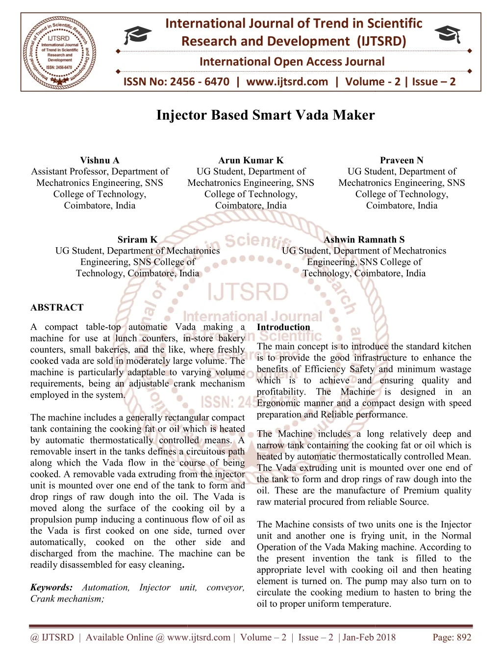
A compact table top automatic Vada making a machine for use at lunch counters, in store bakery counters, small bakeries, and the like, where freshly cooked vada are sold in moderately large volume. The machine is particularly adaptable to varying volume requirements, being an adjustable crank mechanism employed in the system. The machine includes a generally rectangular compact tank containing the cooking fat or oil which is heated by automatic thermostatically controlled means. A removable insert in the tanks defines a circuitous path along which the Vada flow in the course of being cooked. A removable vada extruding from the injector unit is mounted over one end of the tank to form and drop rings of raw dough into the oil. The Vada is moved along the surface of the cooking oil by a propulsion pump inducing a continuous flow of oil as the Vada is first cooked on one side, turned over automatically, cooked on the other side and discharged from the machine. The machine can be readily disassembled for easy cleaning. Vishnu A | Sriram K | Praveen N | Arun Kumar K | Ashwin Ramnath S "Injector Based Smart Vada Maker" Published in International Journal of Trend in Scientific Research and Development (ijtsrd), ISSN: 2456-6470, Volume-2 | Issue-2 , February 2018, URL: https://www.ijtsrd.com/papers/ijtsrd9522.pdf Paper URL: http://www.ijtsrd.com/engineering/food-engineering/9522/injector-based-smart-vada-maker/vishnu-a<br>

E N D
International Research Research and Development (IJTSRD) International Open Access Journal Injector Based Smart Vada Maker International Journal of Trend in Scientific Scientific (IJTSRD) International Open Access Journal ISSN No: 2456 ISSN No: 2456 - 6470 | www.ijtsrd.com | Volume 6470 | www.ijtsrd.com | Volume - 2 | Issue – 2 Injector Based Vishnu A Arun Kumar K UG Student, Department of Praveen N Assistant Professor, Department of Mechatronics Engineering, SNS College of Technology, Coimbatore, India UG Student, Department of Mechatronics Engineering, SNS College of Technology, UG Student, Department of Mechatronics Engineering, SNS College of Technology, Coimbatore Coimbatore, India Mechatronics Engineering, SNS Mechatronics Engineering, SNS College of Technology, Coimbatore, India Sriram K Ashwin Ramnath S Ashwin Ramnath S UG Student, Department of Mechatronics Engineering, SNS College of Coimbatore, India UG Student, Department of Mechatronics Engineering, SNS College of Technology, Coimbatore, India UG Student, Department of Mechatronics Engineering, SNS College of UG Student, Department of Mechatronics Engineering, SNS College of Technology, Coimbatore , India ABSTRACT A compact table-top automatic Vada making a machine for use at lunch counters, in counters, small bakeries, and the like, where freshly cooked vada are sold in moderately large volume. The machine is particularly adaptable to varying volume requirements, being an adjustable crank mechanism employed in the system. The machine includes a generally rectangular compact tank containing the cooking fat or oil which is heated by automatic thermostatically controlled means. A removable insert in the tanks defines a circuitous path along which the Vada flow in the course of being cooked. A removable vada extruding from the injector unit is mounted over one end of the tank to form and drop rings of raw dough into the oil. The Vada is moved along the surface of the cooking oil by a propulsion pump inducing a continuous flow of oil as the Vada is first cooked on one side, turned over automatically, cooked on the other side and discharged from the machine. The machine can be readily disassembled for easy cleaning. Keywords: Automation, Injector unit, conveyor, Crank mechanism; top automatic Vada making a Introduction machine for use at lunch counters, in-store bakery counters, small bakeries, and the like, where freshly are sold in moderately large volume. The machine is particularly adaptable to varying volume adjustable crank mechanism The main concept is to introduce the standard kitchen is to provide the good infrastructure to enhance the benefits of Efficiency Safety and minimum wastage which is to achieve and ensuring quality and profitability. The Machine is designed in an Ergonomic manner and a compact design with speed preparation and Reliable perform preparation and Reliable performance. The main concept is to introduce the standard kitchen good infrastructure to enhance the benefits of Efficiency Safety and minimum wastage which is to achieve and ensuring quality and The Machine is designed in an Ergonomic manner and a compact design with speed The machine includes a generally rectangular compact oil which is heated The Machine includes a long relatively deep and narrow tank containing the cooking fat or oil which is heated by automatic thermostatically controlled Mean. The Vada extruding unit is mounted over one end of the tank to form and drop rings of raw dough into the manufacture of Premium quality raw material procured from reliable Source. The Machine includes a long relatively deep and narrow tank containing the cooking fat or oil which is heated by automatic thermostatically controlled Mean. The Vada extruding unit is mounted over one end of the tank to form and drop rings of raw dou oil. These are the manufacture raw material procured from reliable Source. The Machine consists of two units one is the Injector unit and another one is frying unit, in the Normal Operation of the Vada Making machine. According to the present invention the tank is filled to the appropriate level with cooking oil and then heating element is turned on. The pump may also turn on to circulate the cooking medium to hasten to bring the oil to proper uniform temperature. emperature. by automatic thermostatically controlled means. A removable insert in the tanks defines a circuitous path along which the Vada flow in the course of being cooked. A removable vada extruding from the injector d of the tank to form and drop rings of raw dough into the oil. The Vada is moved along the surface of the cooking oil by a propulsion pump inducing a continuous flow of oil as the Vada is first cooked on one side, turned over The Machine consists of two units one is the Injector unit and another one is frying unit, in the Normal Making machine. According to the present invention the tank is filled to the appropriate level with cooking oil and then heating element is turned on. The pump may also turn on to circulate the cooking medium to hasten to bring the other side and discharged from the machine. The machine can be Automation, Injector unit, conveyor, @ IJTSRD | Available Online @ www.ijtsrd.com @ IJTSRD | Available Online @ www.ijtsrd.com | Volume – 2 | Issue – 2 | Jan-Feb 2018 Feb 2018 Page: 892
International Journal of Trend in Scientific Research and Development (IJTSRD) ISSN: 2456-6470 The Extruder hopper system is filled with the mixer and variable speed extruder drive motor is set at the proper speed depending upon the desired volume of Vada to be produced in them. A small Inexpensive vada fryer has the conveyor and separate extruder that driven from the same shaft without interference with each other.The sprocket for driving the elevator is recessed to receive rod from the conveyor.The method and apparatus for moving object to be fried through a hot frying liquid by producing intermittent waves and eddies in the liquid in desired direction of travel in straight line and also used the stepper motor to make the extruded vada from injector unit to flip and fry the thing on both side of them so that if we cause uniform frying in its process. Fig.1.Flow diagram of existing methodology The Main disadvantage of the existing methodology is given below Floor space is large Relatively High cost Contain minimum number of automated system Time consumption of frying is high due to large space. Electricity waste occurs. However, in our system, these disadvantages are overcome effectively. Proposed System Motivation of the project Our main motivation for doing this project is to improve automation in food technology, so we decide to develop a vada machine, in that we incorporate a compact tabletop machine. The Machine is designed in an Ergonomic manner and which is constructed based on compact shape and size of the machine. The Machine includes a long relatively deep and narrow tank containing the cooking fat or oil which is heated by automatic filled inside them. Comparatively, Cost Effective Hygienic way of Preparation Oil Consumption is Relatively Low Reduce floor Space The proposed system integrates all individual systems under one board. So that the overall cost of the system will be reduced efficiently. Methodology The block diagram of the proposed system is shown in Fig.2. Through literature reviews, we have formulated some of the existing methodologies and designed our system based on the difficulties faced by the existing authors. Existing Methodology There are two methods which are being the major disadvantage followed by the previously. They are 1.Manual Operated 2.No sensor is there to detect the oil at its boiling point;it just works on the principle of just to finish works. The Flow Diagram of the existing methodology is shown below in Fig. 1 Fig.2.Flow diagram of proposed system In the Proposed system, we incorporate several subsystems to make the production more efficient and effective in their performance. In this more over the @ IJTSRD | Available Online @ www.ijtsrd.com | Volume – 2 | Issue – 2 | Jan-Feb 2018 Page: 893
International Journal of Trend in Scientific Research and Development (IJTSRD) ISSN: 2456-6470 system is completely an autonomous one, so that no manpower required of them. The system comprises of sensors and microcontroller in that which the sensor sends the information to the controller and then it will do the action programmed in it, and then in frying pan is also an automated one because in that a rotating flipper is engaged in it, so that the vada will be fried in a proper manner. Moreover, the system which works based on the injector unit in that it consists of hopper system so that it can able carry an amount of raw mixture and incorporate with anIn-Line (Vertical flow motion) using the 2Hp motor employed in the system. Advantages of the proposed system are Integrated systems with Minimal Cost Predetermined shape and size Compact size so its oil consumption is low User-friendly Interface Improvised energy saving The main disadvantages of this proposed system are given below Programming is more complex Electrical components must be handled with caution Time take to reach its boiling point is high. Procedure Flow Components The selection of materials involves the study of their Characteristics, advantages, availability, cost, theuser- friendly property of components that we want to use. In our project, we select each and every component of study thoroughly about them. By proceeding like that only, we had done our selection. The software and device chosen to programme the execution of our idea is MPLAB IDE and AT Mega Board. The Software used to interface user and the machine. The detailed description for selecting components is given below: A.Stepper Motor crank mechanism A stepper motor is a driver used to convert the electrical energy into discrete mechanical energy, the spindle shaft is rotated at the particular speed and it is used to rotate the flipper in the frying pan. The reverse of this is the conversion of mechanical energy into electrical energy and is done by an electric generator, which has much in common with a motor. In this project, we use astepper motor for driving operation. The main purpose of stepper motor used in the project is for rotating the flipper enrolled in the frying pan system. The construction of the stepper motor is shown in Fig.4 The system follows three steps in automating the classroom. They are 1. Sensing 2. Transmission of data 3. Monitoring and Controlling The sensor is the starting point of the process. Once the data is received the microcontroller does its work according to the program stored in it. The Flow diagram is shown in Fig.3 Fig.10 Procedure flow Fig.4.Construction of Stepper motor (Source: www.nptel.ni.in) @ IJTSRD | Available Online @ www.ijtsrd.com | Volume – 2 | Issue – 2 | Jan-Feb 2018 Page: 894
International Journal of Trend in Scientific Research and Development (IJTSRD) ISSN: 2456-6470 The prime mover position would then be able to be instructed to move and hold at one of these means with no position sensor for criticism (an open-circle controller), as long as the engine is painstakingly estimated to the application in regard to torque and speed. B. Thermistor Sensor The sensoris sophisticated devices that are frequently used to detect and respond to electrical or optical signals. ASensor converts the physical parameter (for exampletemperature, blood pressure, humidity, speed, etc.) into a signal which can be measured electrically. Fig 6: Injector unit working (source: www.google.com) And the Major advantage of this system is completely automatic and so with run with 50 to 100 rpm. The injector unit worked based on In-line slider crank mechanism. D.Fryer A Thermistor is sorts about resistor whose imperviousness may be reliant on temperature, that's only the tip of the iceberg something like that over standard resistors. The Thermistor is broadly utilized as inrush current limiter, temperature sensor, Self- resetting In current protectors What's more self- managing warming components. The Thermistor Sensor working is shown in Fig.5. The fryer is one of the important components of this project. Moreover, the word itself describes the use of this component, in this unit we build in the manner of little bit sliding form so that the extrude vada will move toward the outlet of the system. Thus fryer diagram is shown in Fig. 7. Fig.5. Thermistor Sensor working (source: www.elprocus.com) C.Injector The Injector is the major component of this project, moreover, the flour mixture is deposited in the scoop of this unit and the injector will extrude the mixture to the frying pan. A removable dough extruder is movably mounted above the vessel adapted to be positioned over the upstream end of the circuitous flow path. A submerged pump will be arranged in the tank at the upstream limit of the stream way will circularize the cooking medium on gatherings give those transport frameworks to those vada. Thus Injector unit of Hopper system is shown in Fig.6. Fig 7: Frying unit (source: www.indiamart.com) Fryers frequently accompany features for example, such that timers with a capacity of being heard alarm, programmed gadgets on raise and more level the crate under the oil, measures to keep nourishment crumbs from turning into overcooked, ventilation frameworks to decrease browning orders, oil filters to augment the usable term of the oil, and mechanical or electronic temperature controls. @ IJTSRD | Available Online @ www.ijtsrd.com | Volume – 2 | Issue – 2 | Jan-Feb 2018 Page: 895
International Journal of Trend in Scientific Research and Development (IJTSRD) ISSN: 2456-6470 E.Microcontroller The microcontroller used in this project is ATMEGA 328p. The ATMEGA is a microcontroller family which consists of flash memory for program storage; it is similar to Arduino Uno R3. The ATMEGA controller which is a 28 pindual in-line package system (DIP). Moreover, it is used for Temperature monitoring and stepper motor control. The microcontroller diagram is shown in Fig.8. Fig 9.16X2 LCD Matrix (Source: www.amazon.in) A Scoop is a vast, pyramidal formed compartment utilized as a part of modern procedures to hold particulate mixture that has been gathered from theousted air. Scoop is typically introduced in gatherings to take into account a more prominent accumulation amount in them Collecting pan is an element which collects fried vada from the fryer and dried it off. They are like storage system of extruded and fried vada in it. The Table 2 which is listed below contains the overall components and their add-on features used in this project are shown in it. Component Features Fig 8: ATMEGA 328p Controller (source: www.microchip.com) Features: Table 1 describes the complete features of the ATMEGA microcontroller Stepper motor 10kg-cm, 5Kg-cm Feature Cpu type Performance Flash memory SRAM EEPROM Pin count Maximum operating frequency Number of channel Maximum I/O pin Table.1. Features of ATMEGA 328p microcontroller F.LCD 16X2 Matrix Specification 8-Bit AVR 20 MHz 32 KB 2 KB 1 KB 28 pin PDIP, 32 pins TQFP 20 MHZ Controller AT Microcontroller 32 BIT - 28 I/O PINS In-line slider mechanism 1 Mega 328p Injector Crank Power backup touch 16 Thermistor Sensor Generic k-type Sensor LCD Display 16X2 Matrix Display 26 Cables 0.5 SQ mm and other required Framework and other components Stainless steel, Aluminum etc. LCD matrices are great fun; used as a continuous temperature monitor. The temperature measurement is using LM35 an integrated sensor, the sensor converts the input signal to electrical signal by using ADC and the signal is displayed in the display. Sample LCD from Online is shown below in Fig 9. Table.2. Components used in the project Programming The programming is done in MPLAB IDE software. During programming, we have to keep in mind that all @ IJTSRD | Available Online @ www.ijtsrd.com | Volume – 2 | Issue – 2 | Jan-Feb 2018 Page: 896
International Journal of Trend in Scientific Research and Development (IJTSRD) ISSN: 2456-6470 the systems should be automated and they should not get affected by the other parts of the program. lcd_out(1,4,"DIGITAL TEMPERATURE"); lcd_out(2,6,"SENSOR"); delay_ms(1000); Lcd_Cmd(_LCD_CLEAR); // Clear display while(1) { READ_temp(); data_converstion(); display1(); } } Outcome expected There are two types of outcomes expected from this project. We have collected some data from the electric department and our group to achieve the required results. A.Energy Saving The Sample coding is given the future section. Stepper Motor Control void main() { TRISD = 0b0000000; // PORT D as output port PORTD = 0b1111111; do { PORTD = 0b00000011; // energizing two phases at a time Delay_ms(500); // delay of 0.5s PORTD = 0b00000110; Delay_ms(500); PORTD = 0b00001100; Delay_ms(500); PORTD = 0b00001001; Delay_ms(500); }while(1); // loop executed infinite times } LCD Display void READ_temp(void) { temp = ADC_Read(0); temp = temp temp = temp * 100; } void data_converstion(void) { inttostr(temp,temper); } void display1(void) { lcd_out(1,1,"TEMPERATURE="); lcd_out(1,13, Ltrim(temper)); Lcd_Chr_Cp(0xdf); Lcd_Chr_Cp('C'); Lcd_Chr_Cp(' '); } void main() { ADC_Init(); Lcd_Init(); // Initialize LCD Lcd_Cmd(_LCD_CLEAR); // Clear display lcd_cmd(_LCD_CURSOR_OFF); The data from the electric department which controls the power house of the college. The data is then compared with our assumption. The model graph is shown below in Graph.1. * 5/1023; Graph 1: Assumed energy saving @ IJTSRD | Available Online @ www.ijtsrd.com | Volume – 2 | Issue – 2 | Jan-Feb 2018 Page: 897
International Journal of Trend in Scientific Research and Development (IJTSRD) ISSN: 2456-6470 B.Outcome Expected References 1.Journal on “design and development of an automatic dosa maker for indian households” by shaji K.S. in january 2016. From the obtained data we had plotted a graph for the expected outcome in the below graph 2. 2.“Food guide lines and regulation” by FSMA(Food Safety Modernization Act) by U.S. Government on January 4,2011. 3.Paper on “LabVIEW Based Characterization and Optimization of Thermal NasrinAfsarimanesh and PathanZaheerAhamed at University of pune, India . Sensors” by 4.Debkumar Anthropometric Dimensions, For Ergonomic Design Practice, NID India. Chakrabarti, (1997) Indian 5.Paper on title “Stratification of thermoplastic olefins” by Pennington of USA on 1999. Graph 2: Outcome Expected Acknowledgment 6.Amos M. Fester “Automatic Doughnut Making Machine ” united patent US4082033A in April 1976. We take immense pleasure in expressing our humble note of gratitude to our project guide Mr.A.Vishnu Assistant Professor Department of Mechatronics Engineering for his remarkable guidance in doing our project. 7.Herbert T Hunter “Doughnut machine” united patent US2067849A in January 1937. 8.William O Giles “Apparatus and process for continuously producing deep fat fried food products” united patent US2936698A in May 1958. 9.Anderson Edward M “Food cooking machine with control mechanism” united patent US4594941A in June 1986. 10.Philipsloan “Energy electronics, Volume-4;issue-2, in 2009. willy, LegrandJoseph kitchens”.Technology S.Chen, efficient of 11.www.esp32.net 12.www.ebay.in 13.scholar.google.com 14.www.instructables.com 15.www.microchip.com @ IJTSRD | Available Online @ www.ijtsrd.com | Volume – 2 | Issue – 2 | Jan-Feb 2018 Page: 898