Download
1 / 7
70 likes | 78 Views
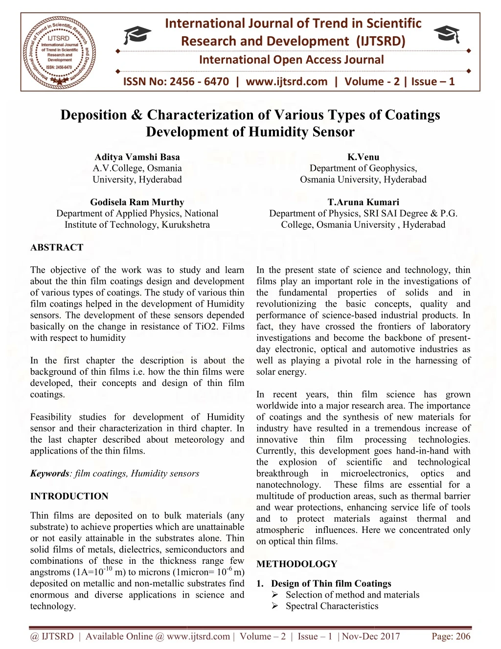
The objective of the work was to study and learn about the thin film coatings design and development of various types of coatings. The study of various thin film coatings helped in the development of Humidity sensors. The development of these sensors depended basically on the change in resistance of TiO2. Films with respect to humidity. In the first chapter the description is about the background of thin films i.e. how the thin films were developed, their concepts and design of thin film coatings. Feasibility studies for development of Humidity sensor and their characterization in third chapter. In the last chapter described about meteorology and applications of the thin films . Aditya Vamshi Basa | K.Venu | Godisela Ram Murthy | T.Aruna Kumari "Deposition & Characterization of Various Types of Coatings Development of Humidity Sensor" Published in International Journal of Trend in Scientific Research and Development (ijtsrd), ISSN: 2456-6470, Volume-2 | Issue-1 , December 2017, URL: https://www.ijtsrd.com/papers/ijtsrd5902.pdf Paper URL: http://www.ijtsrd.com/physics/other/5902/deposition-and-characterization-of-various-types-of-coatings-development-of-humidity-sensor/aditya-vamshi-basa<br>

E N D
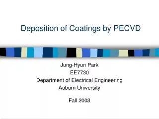
International Research Research and Development (IJTSRD) International Open Access Journal Deposition & Characterization of Various Types of Coatings Development of Humidity Sensor International Journal of Trend in Scientific Scientific (IJTSRD) International Open Access Journal ISSN No: 2456 ISSN No: 2456 - 6470 | www.ijtsrd.com | Volume | www.ijtsrd.com | Volume - 2 | Issue – 1 Deposition & Characterization of Development of Humidity Sensor Aditya Vamshi Basa A.V.College, Osmania University, Hyderabad Godisela Ram Murthy Department of Applied Physics, National Institute of Technology, Kurukshetra Institute of Technology, Kurukshetra Various Types of Coatings K.Venu K.Venu f Geophysics, University, Hyderabad Department of Geophysics, Osmania University, Hyderabad T.Aruna Kumari T.Aruna Kumari SRI SAI Degree & P.G. Osmania University , Hyderabad Department of Applied Physics, National Department of Physics, SRI SAI Degree & P.G. College, Osmania University , Hyderabad In the present state of science and technology, thin films play an important role in the investigations of the fundamental properties of solids and in revolutionizing the basic concepts, quality and performance of science-based industrial products. In fact, they have crossed the frontiers of laboratory investigations and become the backbone of present day electronic, optical and automotive industries as well as playing a pivotal role in the harnessing of solar energy. In recent years, thin film science ha worldwide into a major research area. The importance of coatings and the synthesis of new materials for industry have resulted in a tremendous increase of innovative thin film processing Currently, this development goes hand the explosion of scientific and technological breakthrough in microelectronics, nanotechnology. These films are essential for a multitude of production areas, such as thermal barrier and wear protections, enhancing service life of tools and to protect materials against thermal and atmospheric influences. Here we concentrated only on optical thin films. METHODOLOGY ABSTRACT The objective of the work was to study and learn about the thin film coatings design and development of various types of coatings. The study of various thin film coatings helped in the development of Humidity sensors. The development of these sensors depended basically on the change in resistance of with respect to humidity In the first chapter the description is about the background of thin films i.e. how the thin films were developed, their concepts and design of thin film coatings. Feasibility studies for development of Humidity sensor and their characterization in third chapter. In the last chapter described about meteorology and applications of the thin films. Keywords: film coatings, Humidity sensors INTRODUCTION The objective of the work was to study and learn about the thin film coatings design and development of various types of coatings. The study of various thin film coatings helped in the development of Humidity sensors. The development of these sensors depended ge in resistance of TiO2. Films In the present state of science and technology, thin films play an important role in the investigations of the fundamental properties of solids and in revolutionizing the basic concepts, quality and based industrial products. In , they have crossed the frontiers of laboratory investigations and become the backbone of present- day electronic, optical and automotive industries as well as playing a pivotal role in the harnessing of In the first chapter the description is about the background of thin films i.e. how the thin films were developed, their concepts and design of thin film In recent years, thin film science has grown worldwide into a major research area. The importance of coatings and the synthesis of new materials for industry have resulted in a tremendous increase of innovative thin film processing Currently, this development goes hand-in-hand with the explosion of scientific and technological breakthrough in microelectronics, nanotechnology. These films are essential for a multitude of production areas, such as thermal barrier and wear protections, enhancing service life of tools to protect materials against thermal and atmospheric influences. Here we concentrated only Feasibility studies for development of Humidity r and their characterization in third chapter. In the last chapter described about meteorology and technologies. technologies. : film coatings, Humidity sensors optics optics and and Thin films are deposited on to bulk materials (any substrate) to achieve properties which are unattainable or not easily attainable in the substrates alone. Thin solid films of metals, dielectrics, semiconductors and combinations of these in the thickness range few angstroms (1A=10-10 m) to microns (1micron= 10 deposited on metallic and non-metallic substrates find enormous and diverse applications in science and technology. re deposited on to bulk materials (any substrate) to achieve properties which are unattainable or not easily attainable in the substrates alone. Thin solid films of metals, dielectrics, semiconductors and combinations of these in the thickness range few m) to microns (1micron= 10-6 m) metallic substrates find 1.Design of Thin film Coatings Selection of method and materials Spectral Characteristics Spectral Characteristics Design of Thin film Coatings Selection of method and materials enormous and diverse applications in science and @ IJTSRD | Available Online @ www.ijtsrd.com @ IJTSRD | Available Online @ www.ijtsrd.com | Volume – 2 | Issue – 1 | Nov-Dec 2017 Dec 2017 Page: 206
International Journal of Trend in Scientific Research and Development (IJTSRD) ISSN: 2456-6470 Environmental conditions Requirement / application Selection of Method substrate in suitable fixture or zig and load the work holder. Masking is must for best uniformity of coating. Achieving of vacuum Open the backing valve. The pressure should fall steadily to less than 0.1 torr as the diffusion pump is evacuated. Allow the cooling supply to flow. Switch on the diffusion pump, close backing valve and open roughing slowly. Select GH2 in pirani gauge. If pressure less than 0.1 torr. Close the roughing and open backing valve. Slowly open the baffle valve (high vacuum valve). As soon as the pressure starts rising in pirani GH1. And we may get high vaccum (i.e., 10-7 torr) High tension cleaning The static charge will affect the coating uniformity and adherence. In order to remove the static charge we use the High Tension cleaning. In the H.T cleaning the glow discharge removes any absorbed vapors and gases from the chamber internal surface. Close the high vacuum and open the baffle valve half. Switch on the H.T. button. Apply the low voltage from 0 to 160V or high current about 3 amps and increase it slowly. Now apply the air in to the chamber through needle valve and observe the pressure in the chamber on gauge (0.1). Then rotate the substrate. Due to applied voltage to the aluminum foil it produce ions, bombards with the air molecules in the chamber takes place Glow discharge. After 5 to 7 min, close air admittance valve and switch off the H.T cleaning button. On the completion of H.T cleaning, bring the variac to zero position. Close the air admittance valve and open baffle valve slowly keeping the backing pressure from rising above 0.2 torr. Apply L.T. (Low Tension) to the material Switch on L.T. by selecting rotary switch, CB and L.T electrode selector switch. Rotate the evaporation source selector hand wheel until the required position is numbered. Its position also can be verified through the window. Slowly turn up the variac with the source shutter covered and observe the evaporation through the front window when evaporant is just melt. Uncover the source by means of shutter control knob, unless initial wetting of filament is needed Many types of deposition methods for thin film coating mainly those are 1) Physical vapor deposition method 1) Thermal evaporation 2) EB-gun 3) Sputtering 4) Ion deposition 2) Chemical vapor deposition methods 1) Electrode Deposition 2) Chemical vapor 3) Sol gel 4) Spray paralysis Selection of Material 1. Substrate Material: Optical Glass (for optical coatings) 2. Substrate cleaning material: Iso propyl alcohol, teefal and acids (HCl). 3. Substrate polishing material: Cerium Oxide 4. Coating materials •Metals: Gold, Silver, Aluminum, Copper, Inconel, Platinum, Nickel. •Dielectrics: Silicón dióxido (SiO2), Aluminum Tri oxide (Al2O3) •Conductors: Indium tin oxide (In2O3), Alloy of indium oxides etc. •Semiconductors: Germanium, Silicon •Fluorides: Magnesium fluoride etc 2. EXPERIMENTAL PROCEDURE Cleaning procedure of the substrate Dip the substrate in the Dilute HCL, Then wash the substrate in ordinary water Clean the substrate with Teepol soap solution; again wash the substrate. Dip the substrate in distil water and Dry the substrate Finally clean the substrate in ultrasonic method using alcohol. Loading of substrate in coating plant First we must choose the suitable fixture for the substrate, because different size and shape of substrates used for different applications. Now fix the @ IJTSRD | Available Online @ www.ijtsrd.com | Volume – 2 | Issue – 1 | Nov-Dec 2017 Page: 207
International Journal of Trend in Scientific Research and Development (IJTSRD) ISSN: 2456-6470 in which case, leave the source covered until this is complete. Repeat the process with each filament if necessary, zero variac before changing position of the turret. When the evaporation is completed shutter the source, zero the variac switch off the L.T. (20Volts 170 Amps continuous, 200Amps intermittant) and C.B. Open the air admittance valve, raise the chamber selecting hoist up. Unload the work holder. Handle the fresh films with care. Shut down the unit Evacuate the chamber down to 10-4, and then close the high vaccum valve. Switch off the pirani/penning and diffusion pump. Run the rotary pump for a period of 15-25 min keeping backing valve open. Close the backing valve and switch off rotary pump and close the cooling water supply. Switch off the main switch. Principle of glow discharge: Glow discharge is used to remove the dust particles and atmosphere effects. When applied the (H.T) voltage to the anode and cathode, at chamber Low pressure up to 4*10^-4such as .Due to high voltage ionization will take place and, Highly positive ions moved to the cathode, and electrons (negative charge particles) ,moved to the anode .The below figure shows the diagram of glow discharge. there is attraction force between the neutral atoms and substrate. 3.THIN FILM COATING HIGH REFLECTION COATING If we deposit a material of higher refractive index than that of glass substrate (n=1.52), then we can increase the reflectance of bare substrate at certain wavelength depending up on optical thickness of the film. The first condition is that the refractive index should be greater than that of incident medium and substrate i.e. n0 < ns< nf Consider such a coating on a substrate as shown in figure 2. Figure 2 For maximum reflectance, the interference between the rays reflected from air-film and film-substrate interfaces should be constructive interference, i.e. = 2??? = (2? + 1) /2 (normal incidence) where N is an integer For N=0, ? = ??? Optical thickness = nf × t = / 4 i.e. quarter wave thick. By depositing a quarter wave thick Al on glass (1.52@550nm) we can increase reflectance from 80% (bare substrate) to 85-92 %. Fabrication of High Reflection Coating Fig 1 Then when the velocity of positive ions is impinges or bombardment to the cathode, at the collision place, neutral ions will eject from the cathode. That ions remove the dust particles from the substrate. this is because of before going to the load the substrate we did rubbing ,so that electro static force will create on the substrate so that the Material: (99.9% pure) Aluminum in wire form @ IJTSRD | Available Online @ www.ijtsrd.com | Volume – 2 | Issue – 1 | Nov-Dec 2017 Page: 208
International Journal of Trend in Scientific Research and Development (IJTSRD) ISSN: 2456-6470 Protection coating: Silicon monoxide (SiO) in pallet form Resistance source: helical filament and boat This coating has done in thermal plant (“HIND HIVAC” high vacuum coating plant). So generally every coating follows the same procedure but differ in resistance source. And before apply the low tension to SiO, must enter the air into the chamber. Results Table 1 S.No WAVELENGTH (nm) 1. 400 2. 450 3. 500 4. 550 5. 600 6. 650 7. 700 ANTI REFLECTING COATING Single layer antireflection coating: When a beam m of light traveling in air, refractive index, passes through the a glass plate, refractive index n2,a part of incident light will be reflected on the front an rear sufaces , as shown schematically.The reflectance R of a glass/air interface, defined as, the reflected intensity to the incident intensity ,is a function of the difference in the refractive indices of the media and may be expressed for normal incident as: R=(no-n1)/(n0+n1)2 With ordinary glass plate n2=1.52 the original beam of light is decreased in intensity by this reflected amount ,approximately 4.1%per surface ,making total8.2%.If approximate thin films, refractive index n1,are deposited on the surfaces, these reflection can be reduced, resulting in an effective improvement in the transmission of the glass. This process shown schematically in the below figure, is known as antireflection coating on the glass plate. REFLECTANCE% 93.9 94.0 94.2 94.3 94.2 93.6 92.9 It depends for its operation on almost complete elimination of the light at the upper and lower of the two surfaces of the film n1.For complete elimination of two beams ,the reflected intensities at the upper and the lower boundaries of the film should be equal .which implies that the ratio of the refractive at each boundary should be equal; no/n1=n1/n2; n1= n0*n2. This is the amplitude condition which shows that the film indexn1, should be intermediate between the indices of air and glass. Anti-reflective or antireflection (AR) coatings are a type of optical coatings applied to the surface of lenses or optical devices to reduce reflection. The glass elements in compound lens have a transmittance of only 92. The net transmittance of even a modest number of elements in series can therefore be quite low. Additionally, part of the light reflected at various surfaces eventually reaches the focal plane, where it appears as ghosts. Thus reducing the contrasts of images is especially important for zoom lenses used in photography, which would be completely unusable without AR coatings. In other applications, the primary benefit is the elimination of the reflection itself, such as a coating on eyeglass lenses that makes the objects more visible. In complex systems such as a telescope, the @ IJTSRD | Available Online @ www.ijtsrd.com | Volume – 2 | Issue – 1 | Nov-Dec 2017 Page: 209
International Journal of Trend in Scientific Research and Development (IJTSRD) ISSN: 2456-6470 Where is optical thickness of the film, which is equal to ? R = ????????????? Using equations 1, 2 and 3 we can get reflectance in terms refractive indices as ???????? ????????? As we required zero reflected intensity, the reflectance R should be zero ???????? ????????? i.e. for single layer antireflection coating on a substrate, the refractive index of the film should be geometric mean of refractive indices of substrate and incident medium. For antireflection coating on glass having refractive index 1.52 the film should have refractive index ??= √1.52 = 1.23 However in nature no standard material has this refractive index. The material whose refractive index is closest to 1.23 is MgF2 (1.38 @ 550 nm).other materials ,such as cryolite and chiolite ,have lower indices ,but they are to some extent water soluble ,and films of these materials will not survive in humid environments. Double layer antireflection coating: The refractive indices of most glasses are too low for optimum efficiency of a single layer coating ,If a more effective reduction in reflectance for various glass types required ,this can be achieved with minimum of two films. multilayer λ/4 whose indices decreases from the glass to the outer film surface .For zero reflection of the coating two λ/4 layer systems ,air/n1/n2/glass, where n1 and n2 are the top and base layers respectively ,should be in the following relation: n1/n2 = ng n1 =n2 ng reduction in reflections also improves the contrast of the image. This is specially important in astronomy. Antireflection coatings can range from a simple single layer coating giving nearly zero reflectance to a multilayer system, having virtually zero reflectance over a range of wavelength. Principle: Consider a film of refractive index ?? and thickness‘t’ coated on a substrate of refractive index ?? as shown in the figure 3. When the light incident on such a film the light reflected from both interfaces interferes with each other constructively or destructively depending on the path/phase difference introduced between the two reflected rays. ? in this case ?????????????? (3) ? R = ? (4) ? R = ? = 0 = Path difference between ray1 (reflected from air-film interface) and ray2 (reflected from film-substrate interface) is = 2???cos? For normal incidence i = 00, therefore r =0?, therefore, = 2??? For minimum reflectance the interference should be destructive i.e. = 2??? = (2N+1)/2 where N is an integer For N = 0; i.e. the thickness of coating should be quarter wave optical thickness. Fresnel’s equations for reflectivity at air-film and film-substrate interfaces are given by ??= /4 ????? ????? ????? ????? (1) ??= By considering multiple reflections at both interfaces we can get reflectance of the film R = ????????????????? (2) ?????????????????? @ IJTSRD | Available Online @ www.ijtsrd.com | Volume – 2 | Issue – 1 | Nov-Dec 2017 Page: 210
International Journal of Trend in Scientific Research and Development (IJTSRD) ISSN: 2456-6470 Figure 3 FABRICATION COATING Materials: Zirconium oxide (ZrO2) in Tablet form Magnesium fluoride (MgF2) Aluminum oxide (AL2O3) in pallet form Resistance source: separate boats for each. Procedure is same as for high reflection coating till the high tension cleaning is done. Then switch on the thickness monitor and adjust the transmittance to 92%. Now apply low tension to the boat in order to melt the material for coating. Remove the shutter, read the thickness monitor simultaneously till transmittance is achieved. Nearly, we can achieve above 96% transmission. Turn off the low tension, Switch off the pump and leave the apparatus for 20-30 minutes till the substrate cools down. Then take out the coated sample carefully and measure its properties with the help of spectrophotometer. OF ANTIREFLECTION desired quantity of Results Table 2 S.No WAVELENGTH (nm) TRANSMITANCE (%) Single side anti reflection coating 92.64 Both antireflection coating 93.40 side 1. 400 90.02 2. 450 91.24 93.51 95.29 3. 500 91.49 94.28 96.68 4. 550 91.56 94.54 97.10 5. 600 91.60 94.53 97.26 6. 650 91.73 94.46 97.22 7. 700 91.77 94.39 97.00 @ IJTSRD | Available Online @ www.ijtsrd.com | Volume – 2 | Issue – 1 | Nov-Dec 2017 Page: 211
International Journal of Trend in Scientific Research and Development (IJTSRD) ISSN: 2456-6470 Results Table 3 LENGTH TRANSMISSION% S.NO WAVE (nm) 400 450 500 550 600 635 650 700 1 2 3 4 5 6 7 8 2.30 2.31 2.36 2.44 2.56 2.65 2.68 2.79 CONCLUSION: REFERENCES 1)Ronald R.Willey, a hand book of “Practical design and production of optical thin films”. 2)H.A. Macleod, “Thin Film Optical Filters”, 3rd Edition, Institute of Physics Publishing. 3)James D. Rancourt, optical thin films users hand book. 4)High vacuum Technology: A Practical guide by M. H. Hablanian. 5)Practical guide of Hind High vacuum documents. 6)K.L. Chopra, a hand book of “Practical design and production of optical thin films”. 7)Holland, “a hand book of optical thin film coatings”. 8)Surface and Coatings Technology Volumes 120- 121, November 1999, Pages 303-312. 9)Vacuum engineering by N.S. HARRISH M.sc., M.Inst.p 10)www.google.com 11)www.wikipedia.com 12)www.freepatent.com 13)Langmuir 2007,23, 3473-3477, Highly Sensitive Optical Detection of Humidity on Polymer/Metal Nanoparticle Hybrid Films This Inconel coating has done on spectacles for laser applications. This inconel coating gives the neutral transmission of light over the selected wavelength range. In this way the intensity of light can be decreased uniformly to the desired value. The composition of Inconel is 9% Fe, 76% Ni, and 15% Cr) These type of coatings can be used for many other applications also like night driving filter etc.Material Inconel in wire form in Tungsten filament remaining procedure is samdescribed for other materials . @ IJTSRD | Available Online @ www.ijtsrd.com | Volume – 2 | Issue – 1 | Nov-Dec 2017 Page: 212