Download
1 / 39
460 likes | 694 Views
4.5 FORCE METHOD OF ANALYSIS FOR AXIALLY LOADED MEMBERS. Used to also solve statically indeterminate problems by using superposition of the forces acting on the free-body diagram First, choose any one of the two supports as “redundant” and remove its effect on the bar

E N D
4.5 FORCE METHOD OF ANALYSIS FOR AXIALLY LOADED MEMBERS • Used to also solve statically indeterminate problems by using superposition of the forces acting on the free-body diagram • First, choose any one of the two supports as “redundant” and remove its effect on the bar • Thus, the bar becomes statically determinate • Apply principle of superposition and solve the equations simultaneously
4.5 FORCE METHOD OF ANALYSIS FOR AXIALLY LOADED MEMBERS • From free-body diagram, we can determine the reaction at A = +
4.5 FORCE METHOD OF ANALYSIS FOR AXIALLY LOADED MEMBERS Procedure for Analysis Compatibility • Choose one of the supports as redundant and write the equation of compatibility. • Known displacement at redundant support (usually zero), equated to displacement at support caused only by external loads acting on the member plus the displacement at the support caused only by the redundant reaction acting on the member.
4.5 FORCE METHOD OF ANALYSIS FOR AXIALLY LOADED MEMBERS Procedure for Analysis Compatibility • Express external load and redundant displacements in terms of the loadings using load-displacement relationship • Use compatibility equation to solve for magnitude of redundant force
4.5 FORCE METHOD OF ANALYSIS FOR AXIALLY LOADED MEMBERS Procedure for Analysis Equilibrium • Draw a free-body diagram and write appropriate equations of equilibrium for member using calculated result for redundant force. • Solve the equations for other reactions
EXAMPLE 4.9 A-36 steel rod shown has diameter of 5 mm. It’s attached to fixed wall at A, and before it is loaded, there’s a gap between wall at B’ and rod of 1 mm. Determine reactions at A and B’.
( + ) EXAMPLE 4.9 (SOLN) Compatibility Consider support at B’ as redundant. Use principle of superposition, 0.001 m = δP −δBEquation 1
PLAC AE δP = = … = 0.002037 m FB LAB AE δB = = … = 0.3056(10-6)FB EXAMPLE 4.9 (SOLN) Compatibility Deflections δP and δB are determined from Eqn. 4-2 Substituting into Equation 1, we get 0.001 m = 0.002037 m − 0.3056(10-6)FB FB = 3.40(103) N = 3.40 kN
EXAMPLE 4.9 (SOLN) Equilibrium From free-body diagram + Fx = 0; − FA + 20 kN − 3.40 kN = 0 FA = 16.6 kN
δT = α∆T L 4.6 THERMAL STRESS • Expansion or contraction of material is linearly related to temperature increase or decrease that occurs (for homogenous and isotropic material) • From experiment, deformation of a member having length L is α = liner coefficient of thermal expansion. Unit measure strain per degree of temperature: 1/oC (Celsius) or 1/oK (Kelvin) ∆T = algebraic change in temperature of member δT = algebraic change in length of member
4.6 THERMAL STRESS • For a statically indeterminate member, the thermal displacements can be constrained by the supports, producing thermal stresses that must be considered in design.
EXAMPLE 4.10 A-36 steel bar shown is constrained to just fit between two fixed supports when T1 = 30oC. If temperature is raised to T2 = 60oC, determine the average normal thermal stress developed in the bar.
EXAMPLE 4.10 (SOLN) Equilibrium As shown in free-body diagram, +↑ Fy = 0; FA = FB = F Problem is statically indeterminate since the force cannot be determined from equilibrium. Compatibility Since δA/B =0, thermal displacement δT at A occur. Thus compatibility condition at A becomes +↑ δA/B = 0 = δT −δF
FL AL 0 =α∆TL − F A σ = = … = 72 MPa EXAMPLE 4.10 (SOLN) Compatibility Apply thermal and load-displacement relationship, F = α ∆TAE = … = 7.2 kN From magnitude ofF, it’s clear that changes in temperature causes large reaction forces in statically indeterminate members. Average normal compressive stress is
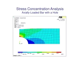
P = ∫AσdA 4.7 STRESS CONCENTRATIONS • Force equilibrium requires magnitude of resultant force developed by the stress distribution to be equal to P. In other words, • This integral represents graphically the volume under each of the stress-distribution diagrams shown.
σmax σavg K = 4.7 STRESS CONCENTRATIONS • In engineering practice, actual stress distribution not needed, only maximum stress at these sections must be known. Member is designed to resist this stress when axial load P is applied. • K is defined as a ratio of the maximum stress to the average stress acting at the smallest cross section: Equation 4-7
4.7 STRESS CONCENTRATIONS • K is independent of the bar’s geometry and the type of discontinuity, only on the bar’s geometry and the type of discontinuity. • As size r of the discontinuity is decreased, stress concentration is increased. • It is important to use stress-concentration factors in design when using brittle materials, but not necessary for ductile materials • Stress concentrations also cause failure structural members or mechanical elements subjected to fatigue loadings
EXAMPLE 4.13 Steel bar shown below has allowable stress, σallow = 115 MPa. Determine largest axial force P that the bar can carry.
EXAMPLE 4.13 (SOLN) Because there is a shoulder fillet, stress-concentrating factor determined using the graph below
r n 10 mm 20 mm = 0.50 = w h 40 mm 20 mm = 2 = P (20 mm)(10 mm) = 0.005P N/mm2 σavg = EXAMPLE 4.13 (SOLN) Calculating the necessary geometric parameters yields Thus, from the graph, K = 1.4 Average normal stress at smallest x-section,
EXAMPLE 4.13 (SOLN) Applying Eqn 4-7 with σallow = σmaxyields σallow = K σmax 115 N/mm2 = 1.4(0.005P) P = 16.43(103) N = 16.43 kN
*4.8 INELASTIC AXIAL DEFORMATION • Sometimes, a member is designed so that the loading causes the material to yield and thereby permanently deform. • Such members are made from highly ductile material such as annealed low-carbon steel having a stress-strain diagram shown below. • Such material is referred to as being elastic perfectly plastic or elastoplastic
*4.8 INELASTIC AXIAL DEFORMATION • Plastic load PP is the maximum load that an elastoplastic member can support
EXAMPLE 4.16 Steel bar shown assumed to be elastic perfectly plastic with σY = 250 MPa. Determine (a) maximum value of applied load P that can be applied without causing the steel to yield, (b) the maximum value of P that bar can support. Sketch the stress distribution at the critical section for each case.
r n 4 mm (40 mm − 8 mm) = 0.125 = w h 40 mm (40 mm − 8 mm) = 1.25 = ( ) σY = K EXAMPLE 4.16 (SOLN) (a) When material behaves elastically, we must use a stress-concentration that is unique for the bar’s geometry. When σmax = σY. Average normal stress is σavg = P/A PY A σmax = Kσavg; … PY = 16.0 kN
EXAMPLE 4.16 (SOLN) • Load PY was calculated using the smallest x-section. Resulting stress distribution is shown. For equilibrium, the “volume” contained within this distribution must equal 9.14 kN.
( ) σY = K EXAMPLE 4.16 (SOLN) • Maximum load sustained by the bar causes all material at smallest x-section to yield. As Pis increased to plastic load PP, the stress distribution changes as shown. When σmax = σY. Average normal stress is σavg = P/A PY A σmax = Kσavg; … PP = 16.0 kN Here, PP equals the “volume” contained within the stress distribution, i.e., PP = σY A
*4.9 RESIDUAL STRESS • For axially loaded member or group of such members, that form a statically indeterminate system that can support both tensile and compressive loads, • Then, excessive external loadings which cause yielding of the material, creates residual stresses in the members when loads are removed. • Reason is the elastic recovery of the material during unloading
*4.9 RESIDUAL STRESS • To solve such problem, complete cycle of loading and unloading of member is considered as the superposition of a positive load (loading) on a negative load (unloading). • Loading (OC) results in a plastic stress distribution • Unloading (CD) results only in elastic stress distribution • Superposition requires loads to cancel, however, stress distributions will not cancel, thus residual stresses remain
EXAMPLE 4.17 Steel rod has radius of 5 mm, made from an elastic-perfectly plastic material for which σY = 420 MPa, E = 70 GPa. If P = 60 kN applied to rod and then removed, determine residual stress in rod and permanent displacement of collar at C.
45 kN (0.005 m)2 = 573 MPa (compression)> σY = 420 MPa σAC = 15 kN (0.005 m)2 = 191 MPa σCB = EXAMPLE 4.17 (SOLN) By inspection, rod statically indeterminate. An elastic analysis (discussed in 4.4) produces: FA = 45 kN FB = 15 kN Thus, this result in stress of And
27 kN (0.005 m)2 = 344 MPa (tension)< 420 MPa (OK!) σCB = EXAMPLE 4.17 (SOLN) Since AC will yield, assume AC become plastic, while CB remains elastic (FA)Y = σY A = ... = 33.0 kN Thus,FB = 60 kN 33.0 kN = 27.0 kN σAC = σY = 420 MPa (compression)
FB LCB AE = ... = 0.001474 m C = EXAMPLE 4.17 (SOLN) Residual Stress. Since CB responds elastically, Thus, CB = C / LCB = +0.004913 AC = C / LAC = 0.01474
EXAMPLE 4.17 (SOLN) Residual Stress. (σAC)r = 420 MPa + 573 MPa = 153 MPa (σCB)r = 344 MPa 191 MPa = 153 MPa Both tensile stress is the same, which is to be expected.
EXAMPLE 4.17 (SOLN) Permanent Displacement Residual strain in CB is ’CB = /E= ... = 0.0022185 So permanent displacement of C is C = ’CB LCB = 0.002185(300 mm) = 0.656 mm Alternative solution is to determine residual strain ’AC, and’AC = AC + AC and C = ’AC LAC = ... = 0.656 mm
P(x) dx A(x) E PL AE ∫0 L δ= δ= CHAPTER REVIEW • When load applied on a body, a stress distribution is created within the body that becomes more uniformly distributed at regions farther from point of application. This is the Saint-Venant’s principle. • Relative displacement at end of axially loaded member relative to other end is determined from • If series of constant external forces are applied and AE is constant, then
CHAPTER REVIEW • Make sure to use sign convention for internal load P and that material does not yield, but remains linear elastic • Superposition of load & displacement is possible provided material remains linear elastic and no changes in geometry occur • Reactions on statically indeterminate bar determined using equilibrium and compatibility conditions that specify displacement at the supports. Use the load-displacement relationship, = PL/AE
CHAPTER REVIEW • Change in temperature can cause member made from homogenous isotropic material to change its length by = TL . If member is confined, expansion will produce thermal stress in the member • Holes and sharp transitions at x-section create stress concentrations. For design, obtain stress concentration factor K from graph, which is determined empirically. The K value is multiplied by average stress to obtain maximum stress at x-section, max = Kavg
CHAPTER REVIEW • If loading in bar causes material to yield, then stress distribution that’s produced can be determined from the strain distribution and stress-strain diagram • For perfectly plastic material, yielding causes stress distribution at x-section of hole or transition to even out and become uniform • If member is constrained and external loading causes yielding, then when load is released, it will cause residual stress in the material