Download
1 / 32
340 likes | 519 Views
OPERATIONS MANUAL Capacitor Duty Thyristor Switch ZCTC-02. TAS Powertek Pvt. Ltd. Corporate Office: W-61, MIDC, Ambad, Nasik - 422010, Maharashtra (India) Tel: +91-(253)-2384038 / 2381090 Email: sales@taspowertek.com. NOTE

E N D
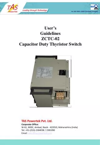
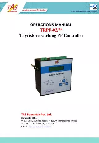
OPERATIONS MANUAL Capacitor Duty Thyristor Switch ZCTC-02 TAS Powertek Pvt. Ltd.Corporate Office: W-61, MIDC, Ambad, Nasik - 422010, Maharashtra (India)Tel: +91-(253)-2384038 / 2381090Email: sales@taspowertek.com
NOTE These instructions do not purport to cover all details or variations in equipment, nor to provide for every possible contingency to be met in connection with installation, operation or maintenance. Should further information be desired or should particular problems arise which are not covered sufficiently for the purchasers purposes, the matter should be referred to our TAS Powertek Pvt. Ltd. office. The contents of this instruction Manual shall not become part of or modify any prior or existing agreement or relationship. The sales contract contains the entire obligations of TAS Powertek Pvt. Ltd. The warranty contained in the contract between the parties is the sole warranty of TAS Powertek Pvt. Ltd. Any statements contained herein do not create new warranties or modify the existing warranty. The reproduction, transmission or use of this document or its contents is not permitted without express written authority. Offenders will be liable for damages. All rights are reserved.
A T S PowerTek Index Ordering Information ------------------ 2 Features ------------------ 3 Specifications ------------------ 5 Mechanical Dimensions ------------------ 7 Main Electrical Parts ------------------ 9 Internal construction Photo -------------- 10 Power Connection ------------------ 11 Power Configuration ------------------------ 12 Control Terminals and Reset switch --------- 13 Front Plate Indications ------------------ 14 Typical Connection of control section -------- 15 Principle of operation ------------------ 18 Usage of line Reactors ---------------------- 21 Usage of Discharge Resistors --------------- 22 Recommendations for usage ---------------- 23 Fault finding Guidelines ------------------ 25 Contact Information -------------------- 29 - 1-
A T S PowerTek • Ordering Information. • ZCTC – Conf / ###/*/$ • Conf :01, 02 or 03 thyristors per switch. • ### :Identifies Current rating in Amp. • Ratings are:040,080,110,140 & 210 • * :C – Without ducting. • D – With ducting. • $ :F – For fast switching mode. • B – Contactor bypass hybrid system. • The type no of the units to be ordered should be mentioned on the Purchase Order. - 2 -
A T S PowerTek • Features: • Provides following protections. • Spike currents protection. • Over current protection. • Thyristor short circuit monitoring. • Thyristor over-temperature cutoff. • Power down monitoring.(including V harmonic protection) • Detection of zero voltage across thyristor switches and turn on of thyristors within maximum ± 6V…. Typical + 3V. • Zero voltage sensing thro’ active sensing circuit for giving the better accuracy and true zero turn ON. • Suitable for 50Hz mains frequency. Optional model with 60Hz is available. • Auxiliary output contact available for enabling/disabling thyristor bypass contactor. (This is for slower correction requirements). When disabled as bypass contactor, it is used as external tripping contact when thyristor fault is detected. This can be useful to disconnect the switch from mains when thyristors are short (damaged). • Provision for inlet air and outlet air ducting. Product is suitable even for IP-54 enclosures. - 3 -
A T S PowerTek • Line Chokes for suppressing instantaneous mains supply spikes currents and / or harmonic currents thro’ capacitors can be selected by the user, the unit can work with series reactors ranging from 0.2% to 16.5% voltage drop reactors. • Fault output (for feedback to controlling relay) of 0V/+12V. • Fault auto-start for spike, over-current, power down and over-temperature faults. • Facility of push button for fault reset. • Electronic Controlling through high speed RISC processor. - 4 -
A T S PowerTek • Specifications: • Mains input: 250V to 500V a.c. Line to Line. 50/60Hz. • Electronics Supply: Built in SMPS capable of handling the transient supply transients and spikes and giving stable output to Electronics even with one phase absent. • Input command to Zero crossing sensing and switch on response time: 10mS max (cold on condition). • Zero crossing sensing limits: ±6V… max. (typical ± 3V…). • Digital I/P & O/P: 0 to 1V for Low & 10V to 12.5V for High. • Electronics, Power section & Earth isolation level: 2.5kV~. • (Cooling fan for heat sink cooling isolation level 1.5kV~.) • Operating Temperature (Ambient): 0°C to 55°C. • Storage Temperature: -10°C to +75°C. • Watt Loss: • Switch in ON condition with full loading.(Maximum value) • Item no.ZCTC-40/2 : 80Watt. Item no.ZCTC-80/2 : 150Watt. • Item no.ZCTC-110/2:200Watt. Item no.ZCTC-140/2:300Watt. • Item no.ZCTC-210/2:450Watt. • Switch in OFF condition. • All types: 30Watt maximum. • (In case if the switch is to be used for the Auto-Capacitor panel for Voltage control; then discharge resistors will be added which may increase the watt loss per switch extra.) • Maximum temperature rise of the casing (Heat Sink) over ambient is 25°C. i.e. 80°C maximum. - 5 -
A T S PowerTek • Auxiliary Contact for bypass contactor/ Thyristor short tripping: Rating 0.5Amp / 240V~ or 2Amp/48V… . • Switch ON time: Maximum 1 cycle of mains. (i.e. time for input control command “High” to thyristor switch-on.: If zero Voltage is sensed.) • Switch OFF time: Maximum ½ cycle of mains. (i.e. time for input control command “Low” to thyristor switch-off.) • Spike current Detection: 2.2 times the peak of max. rated current. • Time: sensing instantaneous. Switch OFF in ½ cycle of mains. • Over current Detection: 1.15 times the max. rated current. • Over temperature Detection: 90°C - Heat-sink temperature. • Maximum permissible dV/dt during Power ON to avoid spurious turn-ON of the switch for ½ cycle: 2000V/mS. • Various Timers: • Thyristor switch ON/OFF & Bypass Contactor command delay = 3 Sec. • Over Temperature Fault tripping to Auto-Resuming time delay = 15 Min. • First Occurrence of Spike Current fault tripping to Auto-Resume time delay = 25sec. Successive 2nd Occurrence after resuming within 5 sec will go in Permanent tripping. • Over Current Detection Time:For 25 sec continuous over-current. Auto Resume time after tripping = 25 sec. • Power Down Fault with: • 1. Presence of V harmonics above 10th harmonic with more than 5% amplitude. • 2. No current detection when ON command is given. • 3. No Voltage detected across thyristors in OFF condition. - 6 -
A T S PowerTek Mechanical Dimensions. ZCTC-02/040 & 080 - 7 -
A T S PowerTek Mechanical Dimensions. ZCTC-02/110, 140, 210. - 8 -
Exhaust Cooling fan. Power Terminals1 A T S PowerTek Control Terminals Fault Reset Push Button. Status Indication LED display Power Terminals2 Power Control Terminals Main Electrical Parts - 9 -
A T S PowerTek Internal Construction Photograph: After Opening the top cover. ZCTC-02/140/C/F - 10 -
A T S PowerTek Electronics SNUBBER SNUBBER Power Connection Schematic ZCTC-02. Power Terminals 1 Power Terminals 2 Note: Any set of power terminal set can be used as either input supply and output towards capacitors. Its for user to define which set of Power terminals are input and which set of Power terminals are output. - 11 -
A T S PowerTek 3 Phase Line configuration Only with ZCTC-**/2. Power Configurations. (Wired by User) The Scheme shown: The most commonly used scheme. Normally, when the Delta connected Capacitor banks are available, this scheme becomes the most cost efficient as well as electrically efficient. ZCTC-02 version is only designed for such schemes. Here Only two phases (I & II) are controlled. This reduces the watt losses. - 12 -
A T S PowerTek Auxiliary NO contacts Control Terminals and Reset switch. CMD: This is the control command Input terminal. High 8 to 14Vdc at this terminal will turn on the switch and 0 to 1Vdc at this terminal would turn off the switch. Maximum current sinked by this terminal is 10mA dc. RST: Reset command for resetting the switch from any fault. Normally this terminal is already wired up with the reset switch provided on the thyristor switch module. This reset switch is seen on the photo shown above. FLT F/B: This is the output terminal from the thyristor switch. This gives 10 to 12.5Vdc output when switch is tripped due to any fault. Maximum sourcing current from this terminal is 10mA. With no fault trip, this terminal is at zero volt dc. GND: This is the ground reference terminal. The CMD or FLT F/B voltage levels are with respect to this terminal. Aux NO: for ZCTC-02----/F it turns on for thyristor fault. For ZCTC-02----/B it is used for actuating bypass contactor. - 13 -
A T S PowerTek Front Plate Indications: • Red color LED indications are for faults. As the indications suggest it means that unit has tripped due to • Unit tripped due to spike current detected. • Unit tripped due to capacitor over Current condition. • Detected that Thyristors in the units are short. • Over Temperature at the heat sink • Shows that no Power is present for at least one of the Power terminals or V Harmonics high level. • Step ON indicates that the switch has turned On the connected capacitor bank. • Power ON indicates that Control electronics for the switch is Powered up. (Supply at Power Control terminals) - 14 -
AO AO INPUT Rph control FLT F/B Yph control FLT RST Thyristor Switch ZCTC-02 Switch number: RESET Bph control CMD A Neutral 12P R R Y Y T B B S GND PowerTek OUTPUT TFB1 C1 C2 TFB2 C3 TFB3 C4 TFB4 TFB5 C5 TFB6 C6 COM GND _ + 12V DC LCPF-02/T Typical connections of Control section in PF controller panel. PF relay of TAS: LCPF-02/T - 15 -
AO AO INPUT Rph control FLT F/B Yph control FLT RST Thyristor Switch ZCTC-02 Switch number: RESET Bph control CMD A Neutral 12P R R Y Y T B B S GND C1 C2 PowerTek C3 C4 OUTPUT C5 TFB1 C6 TFB2 C7 TFB3 C8 TFB4 12P TFB5 TFB6 COM Typical connections of Control section in PF controller panel. PF relay of TAS: SPF-03/T RLY-08/S 12V DC SPF-03/T - 16 -
AO AO INPUT Rph control FLT F/B Yph control FLT RST Thyristor Switch ZCTC-02 Switch number: RESET Bph control CMD A Neutral 12P R R Y Y T B B S GND PowerTek OUTPUT C1 C2 C3 C4 C5 C7 C6 C8 CX - + 12Vdc Regulated Power Supply (200mA) PF correction relay Typical connections of Control section in PF controller panel. PF relay of Other makes. (Other than TAS) - 17 -
A T S PowerTek Principle Of Operation This equipment is a three phase capacitor, ON/ OFF control. Two out of three phases are controlled in ZCTC-02. It’s a known fact that any step voltage given to the capacitor theoretically causes infinite surge current through the capacitors. This gives rise to reduction in life of capacitors as well as switching devices. Also causes undesirable line transients. Here the difference in line voltage and the capacitor voltage (across every thyristor switch) is sensed and whenever it is zero, the capacitors are made to turn ON if input command to turn ON is present. Following Diagram will clarify this point. This diagram even reveals the point that even with capacitor in charged condition, it can be turned ON without spike current. - 18 -
VSW R-Phase Block + _ Ic R A T S Vc Y PowerTek B V B-Phase Block Ic Control Command VSW VC VSW = 0. - 19 -
A T S PowerTek In ZCTC the voltage across every thyristor switch is sensed and when found zero (+3V), checks if input command for that phase is present. If present turns ON the thyristor switch instantaneously(Max response time from zero cross sensing to thyristor turn ON command = 6μSec.) Apart from this, the circuit has been programmed to give the protection to the unit against Capacitor spike current occurrence, capacitor overload, over temperature and false zero crossing detection in presence of Voltage harmonics etc. It has also self monitoring mechanism. In case of thyristor/s is/are short, is indicated thro’ faults and tripping command relay can be configured to turn ON. This thyristor is designed to work almost with any type of Automatic PF control relay unit and provides the reliable operation of switch ON and OFF of the capacitors with zero switching surge current. Entire operation of this is governed by the high speed RISC Microcontroller which ensures the precision accuracy of the unit’s functions. - 20 -
A T S PowerTek Usage of Line Reactors: It is mandatory to use the series line reactors along with all the thyristor switches. The usage of appropriate rating of reactors is mandatory. The reactors can be selected on the basis of the mains supply conditions. Product warranty is valid only if the proper type of reactors are used along with the ZCTC thyristor switches. TAS Powertek recommends to use the following type of reactors depending on the mains supply conditions. - 21 -
A T S PowerTek 25kVAr 415V. 60k 50k 40k 30k 20k 10k 0k 10kVAr 415V. 50kVAr 415V. 100kVAr 415V. Values with RECT-010 reactors. 0 0.5 1.0 1.5 2.0 2.5 3.0 3.5 4.0 4.5 5.0 5.5 6.0 Sec Usage of Discharge Resistors for Faster response: The capacitors after switch off command, can get charged to the DC level which is higher than the Mains voltage peak level. Therefore for the Operations where faster on-off sequences are required, its important to discharge the capacitors by some amount to get the appropriate response time out of the system. For ZCTC-02 type of thyristor switches, following graph gives some typical values of resistors to be used against the response time. Its recommended to use excel program provided by TAS for getting the exact values of the resistors. - 22 -
A T S PowerTek Recommendations for Usage In Auto-PF control panel. • Provide the Discharge resistors across the capacitors. Faster the switching operation, lower should be the ohm value of these resistors. Please be careful while calculating the wattage of these discharge resistors. • Keep the control command and other control wires (+12V) away from any power wiring. It is recommended to route these control wires in separate channels. • Earthing in such electronic panels should be of two types. • a) Power Earthing. • b) Electronic Earthing. • The earth-pits used for such earthing should also be separate. • The earthing connection provided on SMPS of ZCTC module should be connected to power earth of the system. • 4. Every ZCTC should have at least 30mm clearance from all the sides from other ZCTCs or any other electrical item. - 23 -
A T S PowerTek • The panel in which these equipments are mounted should protect them from dust and conductive suspended particles. • It is recommended to put the Fuses or MCBs/ MCCBs in line with every ZCTC. • It is recommended to put a fixed capacitor bank (without suppression chokes but with fuses ) of @10% rating of the total switched kVAr of the system. This helps in terms of absorbing the line transients and provides additional protection to ZCTCs. This also provides the protection to ZCTCs against dV/dt while mains turn ON. • Avoid touching the electronics of the ZCTCs even when they are not energized. • Do not use contactor switching capacitor panel or fixed capacitor switching on the same line as where ZCTCs thyristorised capacitor switch ON panel is installed. • Provide the proper cooling arrangement to the panel so that panel internal temperature does not exceed 50°C. • Regular cleaning with vacuum cleaner helps giving the everlasting performance. - 24 -
A T S PowerTek • Fault Finding Guidelines. • Unit trips with Spike current indication as soon as input turn ON command is given. • : Check the capacitor current by connecting them to mains separately. • It should not be more than the rated current of the switch. • : Check if the jumpers on PCB J1 & J5 are inserted if used along with the detuned reactors of 7% or 14% rating. • : Check if excessive presence of Capacitor current harmonics. This can be checked by putting a fixed capacitor on same line with other electromechanical device and then checking its current harmonics. • : Check the power wiring connections at input of ZCTC and from ZCTC to capacitor banks for any loose/faulty connection. Tighten all the power wiring connection related to that specific ZCTC. • Unit trips with Over current indication during the normal operation. • : Check if the capacitor current is more than the rated current of ZCTC by 1.15 times in any one of the three phases. • : Check the harmonic currents thro’ the capacitors and check if they are causing the peaky natured currents thro’ the capacitors on continuous basis. - 25 -
A T S PowerTek • Unit trips indicating Thyristor Short Circuit. • : Check the thyristor blocks of the unit for any of them to be short. In case they are short, need to replace them. (it is recommended that a person with proper know-how does this job) • : Check if the direct phase to capacitor bank is carrying any current. In such case there is possible earth fault near the capacitor connections / terminals. • Unit trips indicating Over Temperature fault. • : Check if all the cooling fans in ZCTC are working correctly. If not, check if the input supply fuse to them is blown off. Try replacing the fuse if found blown. • : Check the temperature switch wiring. The temperature switch(s) is(are) mounted on heat sink and from there the connection is with the electronic module. • : Check if really the ambient temperature within which the ZCTCs are working is over the desired limit.(50°C). In that case some arrangement to bring down this temp needs to be done. Either by increasing the cooling fans capacity of the panels or by connecting proper air-conditioning arrangement to the panel. - 26 -
A T S PowerTek • Unit indicates Power Down Fault: • : This can happen with input supply is not present to any one of the three phase of power terminals. In such case check the input fuses and/or MCBs power connections. • : This can even happen if any one or more terminals on Capacitor side are in open condition. Check these power connections for possible loose connection or open circuit. Also check the capacitors for any internal dis-connector open circuit. • : In presence of excessive Voltage harmonics, this fault blocks the units from turning ON. Under such case important to use fixed capacitor on same line without any series reactors. This can improve the situation. • After the input command and the steps are on, the unit trips due to Power down indication fault: • : This can happen if any one of the phases shows zero current even is spite of thyristor switch is turned on. This can happen if after the capacitor turn on, one of the input mains fuses blows off or power input MCB trips off. Check for these conditions and correct the same. • : Check for any possible fault with the capacitors and one of the phases do not conduct. - 27 -
A T S PowerTek • Spike current fault does not reset after the 1/2 min delay. • : Possibility that the unit has gone in permanent block mode. If successive two spike current faults are detected by unit or if after first auto resume after the spike current trip, another occurrence of spike current fault within 5 seconds will cause the unit to go in permanent block mode. Give the external reset and see if unit trips again. If unit trips again, try using the guidelines given in point no.1. • Note: It is not recommended to regularly reset the unit if it trips due to spike current fault frequently. In such case try to find the root cause for such event and eliminate the same before resetting the units. • Unit Does not show Power On indication: • Check that the Power control terminals are given the supply. Possibility of one of the phases not present there. • : In case all the phase and Neutral connections are correct, check on control terminals for +12V supply present. In case it is absent, internal SMPS might have failed. • (Please note that the above checks should be done by the trained personnel and any problems arising out of fault finding, our company will not be responsible.) - 28 -
A T S PowerTek Corporate Office/Works/Design Centre: W-61, MIDC, Ambad, Nasik - 422010, Maharashtra (India)Tel: +91-(253)-2384038 / 2381090Email: tas@taspowertek.com Marketing and After-Sales Service:A/58, Kamal Pushpa, K.C. Road, Bandra, Mumbai-400050.Tel: +91-9930513923Email: sales@taspowertek.com Regional Office: Delhi191-B, Ground Floor, Padam Nagar (Filter Market),New Delhi - 110007 (India).Tel: +91-9911615701Email: delhi@taspowertek.com - 29 -
A T S PowerTek