Download
1 / 111
1.21k likes | 1.71k Views
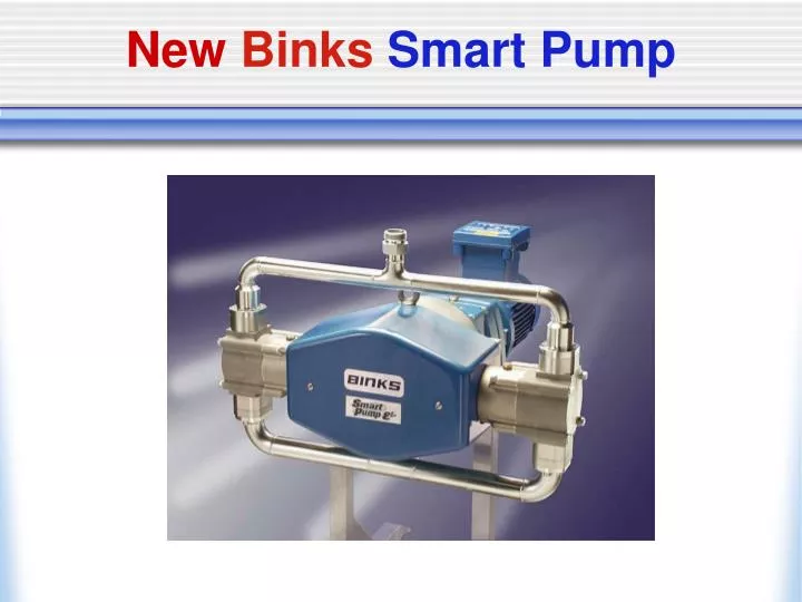
New Binks Smart Pump. Smart Pump Product Line. Electric Smart Pump E2-21 & E2-20: 5 GPM (260 PSI) E2-30: 8 GPM (260 PSI) E 4-60: 16 GPM (260 PSI) E4-90: 24 GPM (203 PSI). Smart Pump Product Line. Accessories: Low Shear Smart BPR ¾” to 2” Connections Smart Card:

E N D
Smart Pump Product Line Electric Smart Pump E2-21 & E2-20: 5 GPM (260 PSI) E2-30: 8 GPM (260 PSI) E4-60: 16 GPM (260 PSI) E4-90: 24 GPM (203 PSI)
Smart Pump Product Line Accessories: • Low Shear Smart BPR • ¾” to 2” Connections • Smart Card: • Automatic controls for “Smart Circ” operation
Why It Was Developed • Fulfill a market need. • Increase process control. • Lower energy and operating costs. • Maintain material integrity. • Abrasive materials (Xirallic) • Provide a pump capable of adapting to customers changing needs.
Description E2-21: 5 GPM • 1.5 HP AC Motor • 40:1 Gearbox • CV Drive Section • Fluid Sections
Description E2-20: 5 GPM • Fluid Sections • CV Drive Section • 40:1 Gearbox • 1.5 HP AC Motor
Description E2-21: 5 GPM CV Cam Slide Rails Cam Follower Tension Springs Swivel Joint
Description E2-21: 5 GPM • AC Motor drives gear box and CV Cam. • Motor is controlled by inverter with either manual or PLC instruction. • The motor frequency is directly proportional to the Fluid Output!
Description E2-30: 8 GPM Main Pump Assembly • Main Components • 2 HP Motor & Gearbox • Main Cam Shaft and Bearings • 2 Cylinders 4 Ball Check • Carriage and Cam Follower • Carriage Support Shaft and Linear Ball Bearing Bushes
Description E2-30: 8 GPM • 2 HP motor reduced through 56:1 gearbox. • Single “constant velocity” cam & carriage assembly ensures no “hard” connections. • (2) horizontally opposed fluid sections provide 8 GPM fluid output.
E2-30 Fluid Section • Quick disconnect fluid section. • Internal piston/fluid seal. • Low pressure bellows seal. • “Run to Failure” back up seal.
Description E4-60 & E4-9016 & 24 GPM Main Pump Assembly • Main Components • 5 HP Motor & Gearbox • Main Cam Shaft and Bearings • 4 Cylinders 8 Ball Check • Carriage and Cam Follower • Carriage Support Shaft and Linear Ball Bearing Bushes
Description E4-60: 15 GPM E4 Smart Pump achieves a reciprocating drive by utilizing a dual cam and cam follower assembly.
Description E4-60: 15 GPM Cam area drives (4) horizontal fluid pistons therefore providing a (4) cylinder true positive displacement operating pump. View showing Min Max Cylinder position
Quick Disconnect Fluid Section “Module” Designed Fluid Section QD Sanitary Clamp piston shaft connection Bolted connections Complete fluid section can be removed by disconnecting (4) sanitary clamps and removal of (8) bolts!
Bellows: “Run to Failure” • Use of secondary chevron style seal behind bellows provides a back up seal and allows for visual indication of bellows failure. • Material flow path • Secondary Seal (vertical piston pump style seal) • Bellows location • Provides visual indication of bellows failure and allows operator time to repair before affecting production.
Beta Site Testing • North American Beta Test Sites • Automotive OEM Testing for: • Component wear (Hz to Flow Ratio) • Constant Flow rate and Pressure • Low Paint Shear • Pump Maintenance • Plant Testing • OEM Facility in IL- Pump in operation since 05/24/06 with “0” downtime. Test Completed and (6) additional pumps were ordered and installed 12/22/06. Original Beta pump still in operation. • OEM Facility in MI – Pump operated on Xirallic Basecoat (white gold) since 06/20/06. Still in operation with “0” downtime. Customer has installed (7) additional pumps. • OEM Facility in TN – Pump in operation since 08/15/06. Test ongoing and customer has ordered (2) additional pumps. • OEM Facility in OH – Pump in operation on Xirallic basecoat since 07/29/06. Test ongoing and customer has ordered (2) additional pump.
E4-60 Beta Site Testing All North American Beta Pumps are still in operation. We have seen NO decrease in “Flow to Hz” ratio signifying no internal wear! Binks will continue to run Beta Test Pumps until failure occurs.
Competitive ComparisonCurrent Technology Existing electric pumps use centrifugal force to supply pressure and flow. This induces shear and wear during 100% of its operation. Air Operated pumps have intrinsic difficulties with exterior icing, internal icing, stalling, repair costs…
Rotary Lobe Pumps Fluid Section Wall • Pump was designed for the food and cosmetic industry. • Utilizes two rotors spinning inside a fluid section to provide flow and pressure. • Rotors do not make contact with wall of fluid section thus allowing material slip by the rotor wings. • Design will not allow thin viscosity materials to build up pressure (i.e. pump will only generate 70 PSI max. on deadheaded solvent system). • Internal slippage does not allow an accurate flow rate to be calculated from pump operation. Area Slippage Occurs Rotors
Rotary Lobe Pumps • Rotors do not make contact with wall of fluid section thus allowing material slip by the rotor wings. • As material slips by rotors shear force is greatly increased. • Material also wears rotor surface thus allowing more material slip. As material slip increases, wear increases as does shear. The longer the pump operates the more shear occurs. • As the rotors wear and shear force increases and pump efficiency decreases.
Rotary Lobe Pumps: Shear Waukesha Pump: • Off color after 150 turns through pump. • Binks Smart Pump: • Still on color after 1450 turns through pump.
Rotary Lobe Pumps: Seals • Mechanical fluid seals are not designed for paint. Paint will migrate between seal faces and will either: • Burn solvent away leaving pigment dust leaking out of the pump. • Paint will gel up pushing seals apart allowing paint to leak on the paint kitchen floor. • Seals must be cleaned and/or replaced on a regular basis in order to maintain acceptable operation.
Turbine Pump Technology Turbine Pumps: • Use multi stage chambers each with a “impeller” blade that centrifugally create pressure and flow. • Each chamber will create shear and increase paint temperature as the impeller blade abuses material. • Temperature increase demonstrates the inefficiency of the pump…temperature increase is lost energy. • A large 10 to 15 HP motor is needed to supply necessary power to impeller blades. • End result is a costly pump that shears material and needs a heat exchanger installed on the circulating system to function properly. Stages Impeller Blade
Vertical Electric Piston Pumps • High costs associated with long stroke electric drives. • Upper packing issues with some materials (i.e. catalyst, white, xirallic, clearcoat…). • Costly control packages needed to eliminate pressure drop issues. • High part costs. • Gearbox or actuator costs and wear concerns. • Need for solvent cup.
Vertical Electric Piston Pumps Centrifugal Motion to Linear Motion: • One of the challenges with an Electric Piston Pump is changing centrifugal motion to linear. • Process must supply: • Smooth consistent linear speed. • Quick changeover for delivering low fluid pulse. • Minimal wear point via no “hard connections”.
Centrifugal Motion to Linear Motion: Actuator Options: • AC Induction motor drives fluid section via a mechanical actuator. • Electric motor drives mechanical actuator via gearbox and coupling. • Function of mechanical actuator is to change motors reversing rotary motion to a vertical reciprocating motion. Limitations: • High cost to meet maintenance requirements. • Top speed limitations. • Slow changeover. • Heat generation. • Hard contact points.
Centrifugal Motion to Linear Motion: Standard Cam Limitations: • Inconsistent fluid and pressure output (pressure swings cannot be overcome with surge chamber). • Hard Connections: Both top & lower cam connections are “hard” mounted and are susceptible to wear (weakest point). • Part Quantity & Service ability: Numerous wear points and difficult to repair properly. • Top speed limitations: High cycle rates even for short periods can cause damage to cam and cam rod connections.
Centrifugal Motion to Linear Motion: Standard Cam Inconsistent Flow & Pressure Output
Centrifugal Motion to Linear Motion: Software By utilizing software to speed up or slow down the motor depending on cam location a “constant velocity” can be achieved. Limitations: • Adds additional cost to capital, installation and controls. • Difficult to retrofit existing installations (no plug & play capabilities). • Concerns with software updates, component availabilities & viruses. • Special wiring & invertors required. • No integrator value.
Centrifugal Motion to Linear Motion: Constant Velocity Cam Binks Solution: • Constant Velocity Cam provides consistent linear velocity via the special profile of the cam. • Mechanical solution to a mechanical problem. • Existing technology. • Simple solution. • Design allows for NO “hard” contact points. • No special software or controls required.
Installation Costs Binks Smart Pump • Plug & Play… • No special wiring. • Use existing VFD. • Possible PDI loop adjustments. • Siphon & outbound hose connections. Graco E-Flo • New VFD required. • New wiring for cam controls. • New operation software. • Siphon & outbound hose connections.
Smart Pump Product Line Accessories: • Low Shear Smart BPR • ¾” to 2” NPT or Sanitary Connections • Smart Card: • Automatic controls for “Smart Circ” operation
Low Shear Smart BPR Pneumatically piloted BPR allows for circulating system to be automatically energized or de-energized… DEPENDING ON THE NEEDS AT THE APPLICATOR!
‘Smart’ Back Pressure Regulation Pilot Control to Regulate Paint System Pressure Range of Connections available as Standard
‘Smart’ Back Pressure Regulation Smart Back Pressure Regulator Large Fluid Area Reduces Velocity, Wear & Shear