Download
1 / 28
280 likes | 442 Views
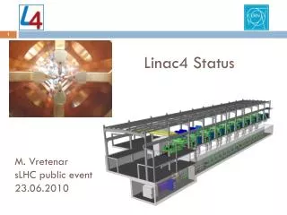
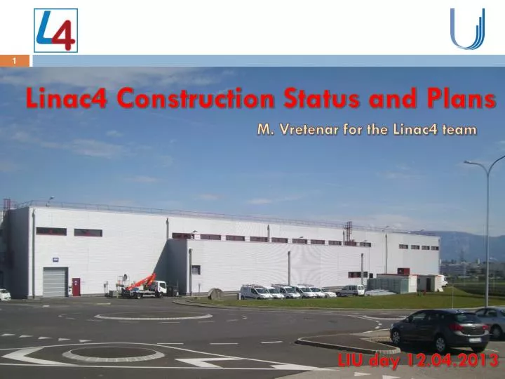
Linac4 Construction Status and Plans. M. Vretenar for the Linac4 team. LIU day 12 .04.2013. Outline. Introduction: layout, progress Schedule and plans Status of different subsystems Main open points Conclusions. But today this is the most important presentation !!.

E N D
Linac4 Construction Status and Plans M. Vretenar for the Linac4 team LIU day 12.04.2013
Outline • Introduction: layout, progress • Schedule and plans • Status of different subsystems • Main open points • Conclusions But todaythisis the most important presentation !!
Layout, parameters, motivations a quick reminder of what everyone should know… Bunch Frequency 352.2 MHz Max. Rep. Frequency 2 Hz Max. Beam Pulse Length 0.4 ms Max. Beam Duty Cycle 0.08 % Chopper Beam-on Factor 65 % Chopping scheme: 222 transmitted /133 empty buckets Source current 80 mA RFQ output current 70 mA Linac pulse current 40 mA Tr. emittance (source)0.25p mm mrad Tr. emittance (linac exit) 0.4 p mm mrad Max. repetition frequency for accelerating structures 50 Hz New 160 MeV H- linear accelerator, will replace Linac2 as injector to the PS Booster. First step of the LIU upgrades. Project approved June 2007, started January 2008. Preparation of the injectors for an upgrade of the LHC luminosity: increase PSB injection energy to reduce space charge (factor 2 in bg2 and brightness). Modern design, providing long term reliability (concerns for Linac2 vacuum ). Flexible operation and reduced loss with new technologies (chopping, H- injection). Higher intensity for non-LHC users. Prepare for a possible high-intensity upgrade (neutrino facility). Test stand
Where do westand? EVM… a first macroscopic point of view… EVM extraction, March 2013 66 % of the project value achieved Including commitments, 79% of the project value achieved or committed. Good correspondence actual cost/earned value, delay due to baseline not up-to-date
When are wegoing to finish Linac4? EVOLUTION OF PROJECT END DATES fromprojectstart to now PROJECT EXPENDITURES actual and initial/presentforecast LS2 LS1.5? With the foreseenconnectiondate advancingby 331 days/year, a simple extrapolation shows thatwewillconnect in September2060. Saturation at14 MCHF/yearof projectexpenditures (CET) mainly due to limitations in availablemanpower: 2013 shouldbe the last saturatedyear! the projectiswelladvanced by now and we are gettingout of saturation → wecanseriously plan for the future and engage for a connection date.
Linac4 – New Masterplan 2013/16 Masterplan, adapted to limited availability of resources during Long Shutdown 1 (2013/14) Transfer 3 MeV to Linac4 tunnel Start high-energycommissioning (12 MeV) End high-energycommissioning (160 MeV) 1 year reliability run Ready for 50 MeV protons as backup to Linac2 Ready for connection Options for connection to the PS Booster: a) Long Shutdown 2 (2018?) or b) intermediatelengthshut-down after end 2016
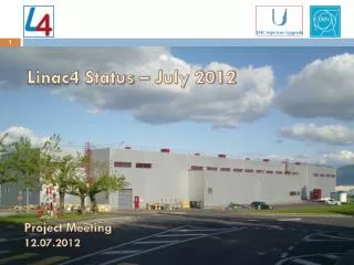
Progress with Infrastructure • Impressive amount of work in 2011/12 • Electrical distribution and CV infrastructure completed • Cabling completed: all cables ready to be connected • Waveguides and circulators installed • Installation of klystrons progressing (50% achieved) • Installation of modulators starting soon
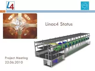
Reminder - Linac4 layout Pre-injector (source, magnetic LEBT, 3 MeV RFQ, chopper line) Three types of accelerating structures, all at 352 MHz. Beam dump at linac end, switching magnet towards transfer line to PSB.
The ion source saga • 2005: decision to copy the DESY RF volume source (reliable, no Caesium) • 2009: DESY-type source completed, equipped with CERN power supplies and RF generator. • May 2010: tests show that it can not operate at 45 kV nominal voltage because of excessive electron current coextracted with the H- that destroyed the electron dump. • End 2010: launched crash programme to build an improved source of CERN design operating in volume mode but upgradable to surface (Cs-based) production. • December 2012: new source ready, but the plasma generator could not produce a useful H- beam. • February 2013: installed DESY plasma generator on CERN extraction: 17 mA of H- obtained, with an emittance of 0.55 p mm mrad (twice nominal). Started RFQ and chopper line commissioning. • Nextsteps: installation of a new version of the source in Linac4, for 3 MeV commissioningtherefrom 09/13. • The Cs version of the source, to beinstalled in August 2014 willbeverysimilar to the SNS source and shouldbe capable of productinghigher H- currents (>40 mA ?).
Conclusions on the ion source It looks like contamination (with low work-function metals: Cs, K, Na, Li,…) is essential for H- production. It seems unlikely that we will reach the nominal 80 mA (*) with this type of source; the options are: a) reduce the requirements: 40 mA out of source are sufficient for all present beams + twice present LHC intensity in 40 turns/ring (160 ms). If and when ISOLDE wants more, should be possible either to increase the number of PSB turns (600 mslinac pulses are now possible instead of nominal 400 ms) or to reduce the chopping factor from the present very conservative 35%. b) build a magnetron-type source, in principle capable of highercurrents, atan additionalcostof 900 kCHF(only initial studies and general design includedin Linac4 project) 3. Development work on the ion source will have to continue in parallel with Linac4 commissioning: present 3 MeV Test Stand will be used for source tests. So far, stability and reliability of the source are excellent: the design is solid. (*) : Nominal Linac4 currents are 80 mA out of source 67 mA out of RFQ 43 mA afterchopping 40 mA to PSB
The RFQ is alive and well ! Original schedule: end of construction September 2009. Actual completion: September 2012 (delays in machining, brazing problems, etc.). Commissioning with beam started on 13.3.2013 (and completed on 28.3!). Late, but commissioned before the 2 RFQs (IPHI and TRASCO) started well before us and whose construction experience was used for the design of our RFQ. The RFQ not only focuses and accelerates the beam as required, but so far it does it in a stable, reliable and reproducible way!
DTL assembly • 1st segment of Tank 1 (out of 2) assembled with girder and drift tubes. • DT alignment tested, vacuum tested, RF tested. • Next steps: • T3S1 delivered, at copper plating • T1S2 & T3S3 delivered, under repair at CERN, will then go to copper plating. • Delivery of all other segments by June 2013. • Drift tubes of T1 and T3S1 completed. Rest to be completed by June 2013. • Assembly, tuning and power test of complete T1 in 2013 Information from S. Ramberger
CCDTL assembly • A team from BINP/Novosibirsk is working at SM18 for the assembly and tuning of the 7 CCDTL modules: • module 2,3,4,5 assembled, leak tight • module 3 assembled with intertankelements, currently being conditioned. • module 2 conditioned to nominal peak power (but not yet nominal pulse length) end of 2012. • A new type of vacuum joints has been successfully tested in March! • delivery of module 1,6,7 in May • assembly of module 1,6,7 in June 2013 • high-power conditioning of all modules finished before the end of 2013 • installation of first modules in the Linac4 tunnel before summer 2013 Information from F. Gerigk
PIMS construction • Module 1builtat CERN (hot prototype, promoted module 1 aftertesting) • Remaining 11 modules + debuncher to bebuiltatNCBJ (Poland). • After 2 years of transfer of technology and machining procedures, the tight specifications are nearly reached for most parts • Qualification could be given for all rough machining steps and green light was given to complete the first 2 cavities • A 2-cell short module was analysed at CERN (dimensions and surface quality, assembling, low power RF tests) with good results • Remaining concerns on nose cone surface quality and stresses introduced by milling => high power test of first cavity needed. • Production status: all 96 discs rough machined, 8 finished; 60 out of 84 rings rough machined, 1 ring finished • New milling machine purchased by NCBJ to speed production, to become operational in summer 2013; new staff hired for a 2nd shift. • first complete cavity foreseen in June 2013 (port welds done by FZ Juelich, brazing of waveguide ring). • 3 cavities expected at CERN in 2013, 4th completed before end 2013 • remaining 8 cavities and auxiliary parts to be delivered to CERN before October 2014 (assembly and EB welding to be done at CERN afterwards). Information from R. Wegner
Dump design and integration Dumps by EN/STI, RP calculations by DGS/RP (C. Maglioni – J. Blaha) Dump core: graphite Shield: steel+boratedconcrete Dose rate <1mSV/h (contact, 1 daycooling time) Fullydismountable for repair / decommissioning
Progress in RF system installation The new Thales 2.8 MW pulsed klystron 10/17 klystrons installed (8 LEP, 2 new)
LINAC4 Modulators Operation on CERN teststand • HV reception tests ongoing • First unit to beinstalled May 2013 Slidesprovided by D. Nisbet
Beam instrumentation • - impressive list of equipment ! • some new designs, to fit in the short available space • progressive commissioning of equipment going on at the test stand.
Beam Interlock System A low-energy beam (160 MeV) presents some dangers, because an accidental beam loss in a critical position can make a hole in the vacuum chamber Machine protection requires a sophisticated Beam Interlock System, integrating Linac and PSB LINAC4 PSB
Work in progress • Precise definition of the modifications to the Linac2 area and lines at the moment of the connection to PSB: • Layout of racks and cablings for B.363 (L2 equipment hall) • Precise definition of additional shielding in the Linac2 area • Precise new layout of measurement lines LBE, LBS (inflector zone, before PSB wall) and way to access them for installation (PS or PSB?).
Interface Linac4 – Linac2 Complex building geometry (entered in FLUKA) Calculationsdonewith the 1 W/m criterion (very conservative for PSB operation) Shieldingcriterion 2.5 mSv/h (non-permanent work place) Radiation dose fromdistributedloss + loss in bendings → ok in Linac2 buildings, apartfrom 2m directly in front of existingcabletray → reduction of cabletray size and specificshielding
Upgrade of measurementlines Upgrade of the beammeasurementlinesat the entrance of PS Booster: - Upgrade for 160 MeV energy (new magneticelements and new measurement technique); - Introduction of appropriatebeam dumps to beusedduringmeasurements
IN CONCLUSION: • Many thanks to all those who have actively contributed to the impressive achievements of these last months! • In particular: • The teams in charge of the building: infrastructure, cabling and supervision. • The ion source team • The different RF teams (6 sections out of 8!) • The survey • The vacuum team • The engineering support • The beam instrumentation team • The beam optics and beam commissioning team
Masterplan – Whatis new New with respect to the Masterplan of June 2012, adapted to LS1 6 months (3 more) for 3 MeV recommissioning in tunnel (more time for measurements + match delayedstart of LS1) Betterdefinition of 2 transfer line phases and activities Beam test time foreseen for eg. PSB stripper tests Clearseparationbetweenbeamcommissioning phases (red) and installation/HW commissioning phases (blue) Keepflexibilityat the end to adapt to anyconnectionschedule
The Linac4 Safety File(s) the project phases 2004 2008 2014/2016 2046? STUDY PROJECT EXECUTION OPERATION DISMANTLING UPGRADE ? Linac4 Safety File (EDMS 905423) June 2008, 91 pages All safety aspects of project, more emphases on civil engineering and machine equipment New Linac4 Safety Folder In preparation by Anne Funken All safety aspects of project, more emphasis on operation. Update of existingSafety File, document followingrecent CERN safety documentation standard (EDMS1177755, 15.6.2012). Approval for tendering of building and execution phase Linac4 Decommissioning Report In preparation (deadline end 2012) Calculation of activation at end of life Estimate of materialquantities for disposal Estimate of the costs (for financial reports) Approval for operation above 3 MeV energy (2014)
Requirements for Linac4 current • Linac4 design 400 ms pulse and 40 mA current correspond to 1014 ppp (twice present ISOLDE with some additional margin). • After connection of Linac4 to the PSB, Linac4+PSB is required to provide the present nominal beams. It is expected to reach the goal for LHC 1-2 years after connection; there are no clear commitments to ISOLDE. • In order to gain some more margin, the maximum Linac4 pulse has been recently extended to 600 ms. • With linac current 20 mA → present beams in PSB + full intensity LHC beam with 40 turns injection. • With linac current 40 mA → maximum ISOLDE beam + full intensity LHC beam with 20 turns injection.
Requirements for Linac4 emittance • Design transverse emittance from ion source 0.25 p mm mrad (rms) • Design transverse emittance at PSB input 0.4 p mm mrad (rms) • We risk to need compromising between current and emittance… Maximum acceptances (no errors, zero current) RFQ : 0.55 p mm mrad Chopper : 0.4 p mm mrad DTL : 0.8 p mm mrad (comparable for other accelerating structures, larger for the transfer line) The PSB can accept a somehow larger emittance