Download
1 / 59
590 likes | 788 Views
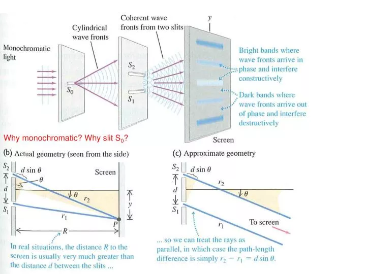
Why monochromatic? Why slit S 0 ?. In the double slit interference pattern: moving the slits farther apart will a) make the pattern spread out b) make the pattern narrower c) have no effect on the spacing of maxima. Q35.3.

E N D
In the double slit interference pattern:moving the slits farther apart willa) make the pattern spread outb) make the pattern narrowerc) have no effect on the spacing of maxima
Q35.3 In Young’s experiment, coherent light passing through two slits (S1 and S2) produces a pattern of dark and bright areas on a distant screen. If the wavelength of the light is increased, how does the pattern change? A. The bright areas move closer together. B. The bright areas move farther apart. C. The spacing between bright areas remains the same, but the color changes. D. any of the above, depending on circumstances E. none of the above
A35.3 In Young’s experiment, coherent light passing through two slits (S1 and S2) produces a pattern of dark and bright areas on a distant screen. If the wavelength of the light is increased, how does the pattern change? A. The bright areas move closer together. B. The bright areas move farther apart. C. The spacing between bright areas remains the same, but the color changes. D. any of the above, depending on circumstances E. none of the above
If you make the source of light dim enough, only one photon at a time will pass through the slits.If you put a piece of film on the wall and wait a long time, (collecting a few billion photon hits)a) there will be no interference pattern, because a photon has to go through one slit or the otherb) there will still be an interference pattern
http://phet.colorado.edu/en/simulation/wave-interferenceWhere in the two-source interference pattern is there a minimum in intensity?
Q35.1 Two sources S1 and S2 oscillating in phase emit sinusoidal waves. Point P is 7.3 wavelengths from source S1 and 4.3 wavelengths from source S2. As a result, at point P there is A. constructive interference. B. destructive interference. C. neither constructive nor destructive interference. D. not enough information given to decide
A35.1 Two sources S1 and S2 oscillating in phase emit sinusoidal waves. Point P is 7.3 wavelengths from source S1 and 4.3 wavelengths from source S2. As a result, at point P there is A. constructive interference. B. destructive interference. C. neither constructive nor destructive interference. D. not enough information given to decide
Where in the two-source interference pattern is there a minimum in intensity?A) II only B) III only C) IV only D) I & II E) III & IV
When two sources interfere, along some lines the fields add and along others they cancel. What about energy conservation?
Interference in thin films • Figure 35.11 (right) shows why thin-film interference occurs, with an illustration. • Figure 35.12 (below) shows interference of an air wedge.
Phase shifts during reflection • Higher index ~ slower wave speed ~ heavy rope ~ fixed end • Lower index ~ faster wave speed ~ lighter rope ~ free end
Because of the phase shift between front and back reflections, any sufficiently thin film will bea) “black” (no reflected light)b) “white” (all colors reflect)
Q35.6 An air wedge separates two glass plates as shown. Light of wavelength l strikes the upper plate at normal incidence. At a point where the air wedge has thickness t, you will see a bright fringe if t equals l/2. 3l/4. C. . D. either A. or C. E. any of A., B., or C.
A35.6 An air wedge separates two glass plates as shown. Light of wavelength l strikes the upper plate at normal incidence. At a point where the air wedge has thickness t, you will see a bright fringe if t equals l/2. 3l/4. C. . D. either A. or C. E. any of A., B., or C.
Newton’s rings • Figure 35.16 below illustrates the interference rings (called Newton’s rings) resulting from an air film under a lens.
Using interference fringes to test a lens • The lens to be tested is placed on top of the master lens. If the two surfaces do not match, Newton’s rings will appear, as in Figure 35.17 at the right.
Nonreflective coatings • The purpose of the nonreflecting film is to cancel the reflected light. (See Figure 35.18 at the right.) • Follow Example 35.7. On Friday I met Dr. Larry Woolf, a PhD physicist who works at General Atomics in San Diego. Larry invented a black paint for cars that reflects IR light. How does it work??
Michelson interferometer • The Michelson interferometer is used to make precise measurements of wavelengths and very small distances. • Follow the text analysis, using Figure 35.19 below.
Chapter 36 Diffraction
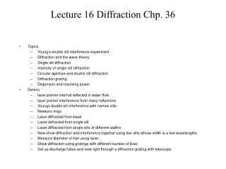
Goals for Chapter 36 To see how a sharp edge or an aperture affect light To analyze single-slit diffraction and calculate the intensity of the light using phasors To investigate the effect on light of many closely spaced slits To learn how scientists use diffraction gratings To see what x-ray diffraction tells us about crystals To learn how diffraction places limits on the resolution of a telescope
Introduction What enables a Blu-ray disc to hold more information than a DVD? Why does light from a point source form light and dark fringes when it shines on a razor blade? We’ll continue our exploration of the wave nature of light with diffraction. And we’ll see how to form three-dimensional images using a hologram.
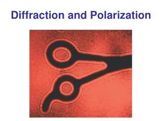
Diffraction According to geometric optics, a light source shining on an object in front of a screen should cast a sharp shadow. Surprisingly, this does not occur because of diffraction.
Diffraction and Huygen’s Principle Huygens’s principle can be used to analyze diffraction. Fresnel diffraction: Source, screen, and obstacle are close together. Fraunhofer diffraction: Source, screen, and obstacle are far apart. Figure 36.2 below shows the diffraction pattern of a razor blade.
Diffraction from a single slit • In Figure 36.3 below, the prediction of geometric optics in (a) does not occur. Instead, a diffraction pattern is produced, as in (b).
Fresnel and Fraunhofer diffraction by a single slit • Figure 36.4 below shows Fresnel (near-field) and Fraunhofer (far-field) diffraction for a single slit. Note how we can guarantee Fraunhofer diffraction by using a converging lens.
Locating the dark fringes Dark fringe appears when wavelets cancel PAIRWISE. First dark fringe appears when there is a half wavelength difference in path across half the slit.
An example of single-slit diffraction Figure 36.6 (bottom left) is a photograph of a Fraunhofer pattern of a single horizontal slit.
We will see that the intensity on the screen looks like this: The actual angle at which the first minimum occurs will depend on wavelength and slit width.
Q36.1 Light of wavelength l passes through a single slit of width a. The diffraction pattern is observed on a screen that is very far from from the slit. Which of the following will give the greatest increase in the angular width of the central diffraction maximum? A. Double the slit width a and double the wavelength l. B. Double the slit width a and halve the wavelength l. C. Halve the slit width a and double the wavelength l. D. Halve the slit width a and halve the wavelength l.
A36.1 Light of wavelength l passes through a single slit of width a. The diffraction pattern is observed on a screen that is very far from from the slit. Which of the following will give the greatest increase in the angular width of the central diffraction maximum? A. Double the slit width a and double the wavelength l. B. Double the slit width a and halve the wavelength l. C. Halve the slit width a and double the wavelength l. D. Halve the slit width a and halve the wavelength l.
Q36.2 In a single-slit diffraction experiment with waves of wavelength l, there will be no intensity minima (that is, no dark fringes) if the slit width is small enough. What is the maximum slit width a for which this occurs? A. a = l/2 B. a = l C. a = 2l D. The answer depends on the distance from the slit to the screen on which the diffraction pattern is viewed.
A36.2 In a single-slit diffraction experiment with waves of wavelength l, there will be no intensity minima (that is, no dark fringes) if the slit width is small enough. What is the maximum slit width a for which this occurs? A. a = l/2 B. a = l C. a = 2l D. The answer depends on the distance from the slit to the screen on which the diffraction pattern is viewed.
Intensity maxima in a single-slit pattern Figure 36.9 at the right shows the intensity versus angle in a single-slit diffraction pattern. Part (b) is photograph of the diffraction of water waves.
You should be able to figure out some “special cases” without the formula! For example, what is the intensity if there is a phase difference of between the top and bottom wavelet? (Compared the intensity straight ahead, where the phase difference is always zero)What angle would this occur at, for a given slit width and wavelength?
Answer: E. The ratio of the amplitude at P to the amplitude at the center of the pattern is equal to the ratio of: Radius to circumference Diameter to circumference Radius to 1.5x circumference Diameter to 1.5x circumference 3/2
Missing Orders From the first missing fringe, you can find the ratio of slit width to separation, using dsin = md=separation asin = a=width If the fifth interference max is missing, (counting the center as zero!) what is the ratio of slit separation to slit width? 1/25 1/5 5 25 Cannot determine without
Missing Orders From the first missing fringe, you can find the ratio of slit width to separation, using dsin = md=separation asin = a=width If the fifth interference max is missing, what is the ratio of slit separation to slit width? c) 5 If the 1st interference max is missing, what does that mean?
Several slits • In Figure 36.13 below, a lens is used to give a Fraunhofer pattern on a nearby screen.
Interference pattern of several slits Figure 36.15 below shows the interference pattern for 2, 8, and 16 equally spaced narrow slits.
Let’s try to understand in general what happens with more than 2 slits, using phasors for the interference. We’ll work this on the board, first for 3 slits. What is the ratio of the intensity of the big peak to the small peak? 2 3 4 9 27
Let’s try to understand in general what happens with more than 2 slits, using phasors for the interference. We’ll work this on the board, first for 3 slits. Here’s a slightly harder question: what is the width of the big peak (from zero to zero), compared to the separation between big peaks? 1/9 1/3 1/2 2/3 3/4
Let’s do 4 slits. What phasor diagram shows the first side zero for 4 slits?
Several slits • In Figure 36.13 below, a lens is used to give a Fraunhofer pattern on a nearby screen.
The diffraction grating A diffraction grating is an array of a large number of slits having the same width and equal spacing. (See Figure 36.16 at the right.)