Download
1 / 34
370 likes | 998 Views
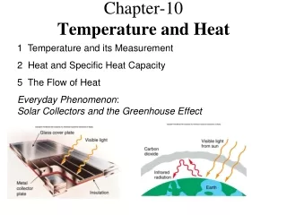
Module 5: Process Integration of Heat and Mass Chapter 10. David R. Shonnard Department of Chemical Engineering Michigan Technological University. Module 5: Outline. The environmental performance of a process depends on both the

E N D
Module 5: Process Integration of Heat and MassChapter 10 David R. Shonnard Department of Chemical Engineering Michigan Technological University
Module 5: Outline The environmental performance of a process depends on both the performance of the individual unit operations, but also on the level to which the process steams have been networked and integrated • Educational goals and topics covered in the module • Potential uses of the module in chemical engineering courses • Review of heat integration concepts • Introduction to the tools of mass integration and synthesis of mass exchange networks - Chapter 10 • Cast study - heat integration of the MA flowsheet
Module 5: Educational goals and topics covered in the module Students will: • learn about efficient utilization of waste streams as raw materials through application of source/sink mapping • are introduced to graphical tools of mass exchange network synthesis, composition interval diagrams and load line diagrams. • apply mass exchange network synthesis to simple flowsheets
Module 5: Potential uses of the module in chemical engineering courses Mass/energy balance course: • dilute contaminant balance calculations around process units • source/sink matching of energy streams Continuous/stagewise separations course: • applications to in-process recovery and recycle of contaminants Design course: • graphical design tools for mass integration of waste streams
Module 5: Analogies between process heat and mass integration Heat Integration the optimum use of heat exchangers and streams internal to the process to satisfy heating and cooling requirements. Tools: 1. Temperature interval diagram 2. Heat load diagram (pinch diagram) Mass Integration the optimum use of mass exchangers and streams internal to the process to satisfy raw material requirements, maximize production and minimize waste generation (water recycle/reuse applications). Tools: 1. Source/sink mapping and diagrams 2. Composition interval diagram 3. Mass load diagram (pinch diagram)
Module 5: Heat exchange networks -key features T - Heat Load Diagram • composite curves • pinch analysis • minimum external utilities Heat exchange network • internal • external [(mCp)1 + (mCp) 2]-1 89% reduction in external utilities Seider, Seader, and Lewin, 1999, “Process Design Principles”, John Wiley & Sons, Ch. 7
Module 5: Heat exchange networks -Illustrative example - before heat integration per sec 1 kg/s, Cp = 1 kJ/(kg-˚C) 2 kg/s, Cp = 1 kJ/(kg-˚C) per sec
Module 5: Heat exchange networks -Temperature - load (pinch) diagram per sec Placement of each load line vertically is arbitrary 2 kg/s Cooling load for external network, 160 kJ/s Heat transfer load by internal network, 140 kJ/s 1 kg/s Heating load for external network, 30 kJ/s 10 ˚C minimum temperature difference defines the pinch
Module 5: Heat exchange networks -Illustrative example after heat integration 82.4% reduction in cooling utility per sec 140 kJ/s transferred 46.7% reduction in heating utility per sec
Module 5: Mass integration: objectives and methods Methods objective is to prepare source streams to be acceptable to sink units within the process or to waste treatment 1. Segregation avoid mixing of sources 2. Recycle direct sources to sinks 3. Interception selectively remove pollutants from source 4. Sink/generator manipulation adjust unit operation design or operation Pollutant-rich streams Pollutant-lean streams El-Halwagi, M.M.1997, “Pollution Prevention Through Process Integration: Systematic Design Tools”, Academic Press
Module 5: Motivating example: Chloroethane process before mass integration Mass balance in terms of CE, the minor component Objective is to reduce the concentration of CE sent to biotreatment to < 7 ppm and a load of < 1.05x10⁻⁶ kg CE/s El-Halwagi, M.M.1997, “Pollution Prevention Through Process Integration: Systematic Design Tools”, Academic Press
Module 5: Motivating example: Chloroethane process after mass integration Interception CE load to biotreatment = 2.5x10⁻⁷ kg/s Recycle El-Halwagi, M.M.1997, “Pollution Prevention Through Process Integration: Systematic Design Tools”, Academic Press
Module 5: Mass Integration Tools:Source-sink mapping the purpose of source-sink mapping is to determine if waste streams can be used as feedstocks within the process - direct recycle Recycle source “a” directly A range of acceptable flowrates and composition for each sink , “S” or mix sources “b” and “c” to achieve the target flowrate - composition using a Lever Rule - like calculation El-Halwagi, M.M.1997, “Pollution Prevention Through Process Integration: Systematic Design Tools”, Academic Press
Module 5: Source-sink mapping: acrilonitrile (AN) process before recycle 0 ppm NH3 0 ppm AN required ≤ 10 ppm NH3 may contain AN 450 ˚C, 2 atm 2-phase stream always with 1 kg/s H2O but no H2O in the AN layer mass fraction of AN always equal to 0.068 NH3 equilibrium CW = 4.3 CAN NH3 partitioning CSTEAM = 34 CPRODICT
Module 5: Source-sink map acrilonitrile (AN) process Sinks for water Sources for water
Module 5: Flow rates of condenser and fresh water sent to Scrubber
Module 5: Mass balances on AN units for remaining flow rates and compositions Aqueous streams from condenser and distillation column 4.7 kg/s H2O 0.5 kg/s AN 12 ppm NH3 From fresh water supply 1.0 kg/s H2O 0 kg/s AN 0 ppm NH3 Scrubber Gas stream from condenser 0.5 kg/s H2O 4.6 kg/s AN 39 ppm NH3 to decanter ? kg/s H2O ? kg/s AN ? ppm NH3
Module 5: Flow rates and compositions from Scrubber to Decanter And similarly for other units
acrilonitrile (AN) process after recycle freshwater feed 30% of original AN production rate increased by 0.5 kg/s; $.6/kg AN and 350 d/yr = $9MM/yr rate of AN sent to biotreatment is 85% of original 60% of original
Module 5: Mass exchange network (MEN) synthesis 1. Similar to heat exchange network (HEN) synthesis 2. Purpose is to transfer pollutants that are valuable from waste streams to process streams using mass transfer operations (extraction, membrane modules, adsorption, .. 3. Use of internal mass separating agents (MSAs) and external MSAs. 4. Constraints i. Positive mass transfer driving force between rich and lean process streams established by equilibrium thermodynamics ii. Rate of mass transfer by rich streams must be equal to the rate of mass acceptance by lean streams iii. Given defined flow rates and compositions of rich and lean streams
Module 5: Mass integration motivating example - Phenol-containing wastewater El-Halwagi, M.M.1997, “Pollution Prevention Through Process Integration: Systematic Design Tools”, Academic Press Outlet streams for recycle or sale Mass separating agents to waste water treatment - Minimize transfer to waste treatment - to wastewater treatment
Module 5: Outline of MEN synthesis 1. Construct acomposition interval diagram(CID) 2. Calculate mass transfer loadsin each composition interval 3. Create acomposite load linefor rich and lean streams 4. Combine load lines on a combined load line graph 5. Stream matching of rich and lean streams in a MEN using the CID
Module 5: Hypothetical set of rich and lean streams - stream properties Equilibrium of pollutant between rich and lean streams y = 0.67 x
Module 5: Composition interval diagram - a tool for MEN synthesis x scale matched to y scale using y = 0.67 x
Module 5: Mass transfer loads in each interval Rich Streams negative mass load denotes transfer out of the stream
Module 5: Composite load line for the rich stream Region 1 & 2 Region 3 Region 4 Region 5
Module 5: Combined load line for rich and lean streams mass load to be added to lean stream externally mass load to be transferred internally Rich Stream can be moved vertically mass load to be removed from rich stream by external MSA
Module 5: Heat integration of the MA flowsheet -9.23x10⁷ Btu/hr 2.40x10⁷ Btu/hr 9.70x10⁷ Btu/hr Reactor streams generate steam -4.08x10⁷ Btu/hr Without Heat Integration
Module 5: Heat integration of reactor feed and product streams
Module 5: Heat integration of absorber outlet and recycle streams
Module 5: Heat integration summary Greater energy reductions are possible when steam generated from the reactors is used for the reboiler, purge and feed heaters 76.8% reduction 27.4% reduction
Module 5: Recap • Educational goals and topics covered in the module • Potential uses of the module in chemical engineering courses • Review of heat integration concepts • Introduction to the tools of mass integration and synthesis of mass exchange networks - Chapter 10 • Cast study - heat integration of the MA flowsheet