Download
1 / 18
180 likes | 325 Views
LSST Camera Electronics John Oliver . Camera Electronics Working Group. John Oliver (Camera Electronics Project Manager) Nathan Felt, Sarah Harder - Harvard University – Paul O’Connor, Veljko Radeka Brookhaven National Laboratory – John Geary

E N D
Camera Electronics Working Group John Oliver (Camera Electronics Project Manager) Nathan Felt, Sarah Harder - Harvard University – Paul O’Connor, Veljko Radeka • Brookhaven National Laboratory – John Geary - Harvard Smithsonian Center for Astrophysics - Mitch Newcomer, Rick Van Berg (Electronics System Engineer) - University of Pennsylvania - Klaus Honschied - Ohio State University - Mike Huffer • Stanford Linear Accelerator Center – Chuck Britton, Paul Stankus, Nance Ericson Oak Ridge National Laboratory DoE Site Review
Focal plane readout : The challenge • Large focal plane 201 Sensors, 3.2 Gpixels, 64 cm focal plane • 10 u pixels, 0.2 arc-sec/pixel • High speed readout 3 spec, 2 sec goal • Low read noise, sky noise dominated > ~ 5 e rms • Sensor temp ~ - 100C • High dynamic range Full well ~ 100,000 e • High crosstalk immunity ~ 80 db • Fully synchronous readout across entire focal plane • Large number of sensor pads (signals) 150/sensor ~ 30,000 pads total • High vacuum environment contamination control • Minimization of vacuum feedthroughs DoE Site Review
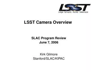
Camera Overview (Drawing courtesy Martin Nordby – SLAC) Utility Trunk Cold Plates BEE Module Cryostat outer cylinder Focal Plane fast actuators Raft Tower (Raft with Sensors + FEE) L3 Lens in Cryostat front-end flange Filter Changer rail paths Shutter L1/L2 Housing Camera Base Ring Filter Carousel main bearing Filter in stored location L1 Lens Camera Housing Cut-Away View of Camera Assembly(false-color image) L2 Lens DoE Site Review Filter in light path
Focal plane readout : The strategy • Utilize highly segmented sensors to allow modest read speed • 16 segments (ports) / sensor 500 kHz readout @ 2 second read • “Raft” based electronics package 9 x 16 = 144 ports per raft • Electronic package located within Dewar to avoid ~30k Dewar penetrations • FPA electronics packaging requirement All electronics must live in “shadow” of raft footprint ~ 125 mm x 125 mm • 21 rafts ~3k readout CCD output ports (source followers) • Data output on one optical fiber per raft 144 Mpixels/2 sec ~1.4 Gbps on fiber • All raft electronics controlled by single “Timing & Control Module” for focal plane synchronicity Timing/Control Port • Timing/Control Port also used for “Engineering Interface” for CCD studies & setup DoE Site Review
Focal plane readout : The implementation • Separate raft functionality into “Front End” and “Back End” Electronic packages • Front End Electronics (FEE) • Cold zone Near FPA temperature ~ -100 C • Analog functions only • Dual Slope Integration for signal processing • Transmits signals as differential analog to Back End Electronics (BEE) • 16 channel ASICs (“Standard” 0.25u CMOS) • Clock level translation • Conversion of logic level signals (LVDS) to CCD Clock levels • Clock timing signals (LVDS) come from BEE • 16 channel ASIC (HV CMOS process) DoE Site Review
Focal plane readout : Implementation con’t • Back End Electronics (BEE – Harvard deliverable) • “Cool” zone ~ - 40 C • A/D , D/A, and digital functions • A/D Conversion • 16 bit commercial ADCs in “chip scale” (~ 7mm x 7mm) packages • 288 packages per raft • D/A conversion • CCD bias levels • Clock Hi/Lo levels • Transmitted to FEE as analog levels on flex cable • FPGA functions • Detailed readout control : Slave to Timing & Control Module • Data fiber controller/driver (Xilinx “Rocket i/o”) • Engineering interface DoE Site Review
Focal plane readout : Implementation con’t • Vacuum compatibility • All internal cabling Polyimide (eg Kapton) flex • All printed circuit boards Polyimide rigid, conformal coated • All materials cleaned, baked, “certified” for hi-vac compatibility • Electronics heat removal • Copper core pcbs for heat transport from components • Copper bars for heat transport to “cold” and “cool” plates (corresponding to “cold” and “cool” zones) DoE Site Review
Filters Shutter mechanism FPA FEE Back End Electronics Timing/control crate External services Camera Electronics distribution Cryostat • Timing & Control Module • Shutter Controller • Filter Controller • Thermal Controllers • Electromechanical Actuator Control • Guide Sensor Control • Power Conditioning • Ethernet hub • Thermal controllers • Vacuum controllers Data Fibers Power & cooling Ethernet DoE Site Review
Timing/Control & Engineering Interface bus FEE FEE FEE FEE FEE BEE BEE BEE BEE BEE Pixel & metadata Timing & Control Shutter Filter x-y FPA Actuator From Camera Control Data Fibers to DAQ Ethernet Hub Guider Thermal Zone 1 Controller # n Camera data/control flow DoE Site Review
Electronics support cage Packaging : Front End Electronics DoE Site Review
Rafts and Front End Electronics (Drawing courtesy of Martin Nordby, SLAC) Sensor Packages Raft mount points • Key parameters • All 9 sensors flat to 6 microns • Raft and mount to Grid stable down to 173 K Raft Flex cables and Thermal Straps FEE Boards FEE cage Raft TowerFront-side View Aluminum-Nitride Raft structure Thermal Straps Partially Assembled RaftFront-side View Sensor Package mounting balls DoE Site Review
Packaging/Cooling detail - BEE • 8x 16-bit ADCs per “octal” ADC card 40 mm x 80 mm • Copper core pcb technology for heat removal (courtesy “Dynamic Detail Inc”) DoE Site Review
Packaging/Cooling detail - BEE • 6x octal ADCs per ADC mother board 48 ch • Recently reduced to 24 ch • Copper bars transfer heat to cage frame, then to “cool” plate DoE Site Review
Packaging/Cooling detail - BEE • 6x ADC mother boards per raft BEE module 288 (now 144) channels per complete unit • “Fiber Driver Board” at base • Cage not shown DoE Site Review
Raft Electronics packaging (1 of 21) Raft FEE BEE DoE Site Review
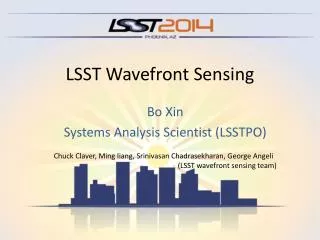
Timing & Control • Single “Timing & Control Module” fanned out to 21 rafts • State machine based timing & control : all features programmable through flexible register structure • Entire FPA readout proceeds on “Go” signal from Camera Control • Timing & Control Unit provides “Engineering” interface for low speed connection to sensor data for • Setup • Diagnostics DoE Site Review
Conclusions & status • Focal Plane Array Science Array • Most critical subsystem • Conceptual design in place • Development (engineering) plan in place • Manpower identified • Prototype FEE & BEE boards available for testing fall ‘06 • Monitor, Control, & Guider Electronics • Functional requirements (placeholders) identified • Command protocol understood • Detailed engineering not yet commenced • Manpower to be assigned • Grounding, shielding, command & data flow • Conceptual design in place DoE Site Review