Download
1 / 42
420 likes | 580 Views
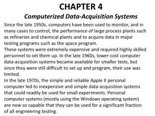
Elec 471 Embedded Computer Systems Chapter 7, Data Acquisition Systems. By Prof. Tim Johnson, PE Wentworth Institute of Technology Boston, MA Theory and Design for Mechanical Measurement by Richard Figliola. Content. Sampling concepts Sample Rate Alias Frequencies Amplitude Ambiguity

E N D
Elec 471 Embedded Computer Systems Chapter 7, Data Acquisition Systems By Prof. Tim Johnson, PE Wentworth Institute of Technology Boston, MA Theory and Design for Mechanical Measurementby Richard Figliola
Content • Sampling concepts • Sample Rate • Alias Frequencies • Amplitude Ambiguity • Selecting sample rate and data number • Analogue Converters: ADC and DAC • Data Acquisition System Overview • Data Acquisition Component parts • Data Communications • Single vs. Double Ended • Serial: RS232, SPI, I2C • Parallel: GPIB, • Wireless
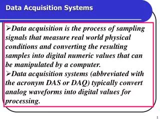
Chapter introduction • Concept: analogue signals are continuous in amplitude and time while digital signal are discrete (meaning countable). • Digital signal are non-continuous in amplitude and time however individual data signals are valid representations for amplitude and time. • Sampling is the process of making a continuous signal discrete. • The problems and solutions for digitization are presented.
Introduction to sampling • The question that confronts the digital engineer is how well does the sampling represent the analogue signal? • The answer depends upon : • the frequency content of the signal • The size of the period between sample (ADC frequency) • The total sample period of the measurement
Sampling Concepts • A Discrete Fourier Transform (DFT) conveys all the information needed to reconstruct a Fourier series of a continuous signal from a digital signal. • Fourier analysis will provide some guidelines for sampling continuous data. • Let δt be the interval between samples so the sample rate (sample frequency, fs) is fs = 1/δt
Nyquist Frequency • The sampling theorem states that to reconstruct the frequency content of a signal accurately the sample rate fs must be more than twice the highest frequency content of the signal. • The highest frequency of a signal that can be sampled at any particular sampling rate is called the Nyquist frequency . • Let fm represent this maximum frequency. • fs > 2 fm substituting for fs we get 1/δt> 2 fm • Inverting the equation reverses the > sign: δt< 1/2fm
Effect of sample rate Lost amplitude content Lost frequency content
Alias Frequencies • When the signal is sampled at a sample rate that is less the 2fm the higher frequency assumes the identity of a lower frequency. • An example of this is when the wagon wheel on a covered wagon in the early days of television would turn backwards. • The folding point of the aliasing phenomenon seen in the next slide is at the Nyquist frequency: fN = fs/2 = 1/2δt
Frequency aliasing diagram Frequency values seen will increase until the signal frequency reaches the Nyquist frequency then they will begin to decrease and can even go back to zero until they start to increase again.
Amplitude Ambiguity • As long as the sampling rate is twice the sampled signal’s highest frequency the frequency content remains valid for the digital signal but this rule doesn’t apply to amplitude fidelity. • Consider N an integer. If for some value of N, N*δt equals the time period, Ts, of the frequency of the sampled signal then the DFT (the digitized signal) will contain the correct values for the amplitude of the signal. • This can be seen in time diagrams and frequency spectrum diagrams of a signal on the next slide.
This phenomenon is known as signal leakage (to adjacent frequencies) The truncated wave creates a modulated signal thus creating sidebands that suck the power from the correct amplitude value shown at the sampled frequency
Sampling summary • The number of data points and the sample rate should be chosen to satisfy the criteria of fs > 2 fm δf = 1/Nδt = fm/N In general, set fs ≥ 5 fm
Digital to Analog Converter • An DAC is an M-bit device that converts a digital value into an analog voltage. • Shown on the next slide is a basic DAC device that uses an M-bit register with a weighted resistor network and an operational amplifier. • The resistors have a common summing point. • The resistor associate with the MSB has a value of R and each subsequent resistor value is doubled according to 2(|Bit#+1-M|)R. • The output current is • The output voltage is Eo = IRr
DAC schematic This is a design you can build yourself. The output bits control the switching of the source voltage to each resistor.
Analog to Digital Conversion • An ADC converts a voltage into a binary value by a process known as quantization. • The analog side of the ADC is characterized by its full scale voltage range, VFSR. • Resolution, Q, is the smallest voltage increment that will cause the LSB to change. Q = VFSR/2M • Quantization error is caused by a voltage value falling between two different digital values. It behaves as noise imposed on the digital signal. • The error value can vary between the LSB step value and ½ LSB. The span of the quantization error is the same as the resolution.
Quantization, Bias, & Saturation Making the quantization symmetric about the input shifts the dotted line, the presumed linear input voltage thus changing the bias constant v in the linear equation y=mx + b. The bias only needs to be moved a negative ½ LSB voltage.
Conversion errors • Sources of errors in the output voltage can be resolved into hysteresis, linearity, sensitivity, zero and repeatability errors . These were covered in Chapter 2. • The extent of the errors depend on the particular method of ADC. • Other factors include settling time, signal noise during sampling, leakage, and temperature.
Successive Approximation Converters • In a SAC ADC a comparator compares the input voltage to a reference voltage derived from a DAC value based upon the binary evaluation using the MSB first and setting each subsequent bit higher (1) or lower (0) until all the bits in the ADC register are filled. • In this scheme the starting reference value is ½ FSR or 0x80 for an eight bit converter. • If the input voltage is higher(lower), the MSB of the register is set at 1(0) and then the next bit is evaluated after the register value is converted into the reference voltage by the DAC converter. • The time of conversion is Mbits*bit conversion speed. This conversion can be effect by noise at the instance of conversion giving weighted value to small noise. • The converter requires the input voltage be held constant during the conversion process so a Sample and Hold is required on the input.
Ramp (integrating) Converters • Low-level voltage measurement use this converter for its low-noise features. • The main components are a comparator, a voltage generator that increases linearly that the name ramp, and the counter and the M-bit register. • The basic principle of this converter is that as a reference voltage is increased on a timed basis, the comparator flips thus stopping the comparison. The counter is then used to determine the input voltage based on time taken by the ramp generator to cross the input voltage.
Ramp Converter block diagram Using a capacitor of known fixed value charged by a fixed current source the time to charge can be calculated. The coulombs charge C, is related to the current flow (q=It) divided by the voltage (C=q/V). Since the charge is known, the rate of current flow is know, substituting in It solves for V with the value of the count known (the count stops when the comparator flips determining the time, t): V=It/C
Parallel Converters • Parallel are fast as one comparator is used for each bit. • A highly stable reference voltage divides the voltage through a precision resistor network with the MSB resistor dropping the voltage by ½ VFSR and so on down the line by ½ at each branch. • Time for conversion is only the time for one comparator to switch. • Very fast but expensive.
Delta Sigma Conversion • The sigma-delta (Σ-Δ) ADC is the converter of choice for modern voiceband, audio, and high-resolution precision industrial measurement applications. The highly digital architecture is ideally suited for modern fine-line CMOS processes, thereby allowing easy addition of digital functionality without significantly increasing the cost. Because of its widespread use, it is important to understand the fundamental principles behind this converter architecture. * *http://www.analog.com/static/imported-files/tutorials/MT-022.pdf
One-bit comparator output Source http://www.analog.com/static/imported-files/tutorials/MT-022.pdf Source http://en.wikipedia.org/wiki/Sigma-delta_converter
Oversampling filter effects Source http://www.analog.com/static/imported-files/tutorials/MT-022.pdf
Signal to Noise Ratio in ADC • The SNR is improved by higher resolution as seen in the table below. • Digital SNR is defined as the ratio of power in the signal to the noise power thus the larger the number the smaller the noise and the clearer the signal: SNR[dB] = 20 log 2M Note: If there is an amplifier in the ADC circuit then the resolution in Table 7.2 modifies the formulas to 20 log(Gain*2M) and Q = VFSR/(Gain*2M)
Data Acquisition Systems • This is a systematic look at the usage for an ADC converter after the value is sensed. • A DAS is that portion of a measurement system that quantifies/store/displays/controls the value.
Block Diagram of a DAS INPUTS→MULTIPLEXER→ADC→CONTROLLER→OUTPUT:STORAGE/DISPLAY/DATA-COMM I/O
DAS Components • A voltage divider (lower right) is a very handy and simple two that is used for two different purposes. • One—converts a current source sensor into a voltage source for reading by an ADC. R1 becomes a current limiting resistor. • Two—converts a high voltage into a lower voltage readable by an ADC. • A shunt circuit (lower left) also converts a current source into a voltage source if the current is “low”.
Nulling Circuit • In order for an ADC to work correctly the signal has to have extraneous voltages removed. • The nulling circuit sets a sensor to zero if it’s output should be zero. Its use is like the adjustment knob on a bathroom scale when no one is standing on the scale except the scale mechanism. This circuit is essential a Wheatstone bridge circuit that has a potentiometer across three terminals. It is used to balance the potential between CH+ and CH- (equal to zero).
Single and Double Ended sources • A single-ended connection has one signal line (+High) measured relative to ground. Single ended are the usual connections we use; not obvious when using local grounds is all the devices share a common ground. • A double-ended connection uses two signal lines due to different ground potential at either end. A signal high is paired with a signal return to isolate the signal from the local grounds (prevent ground loops).
Pull-up/Pull-down Resistor • In circuits where an input level is being detected, have a pull-up resistor can save the battery power. • In the accompanying diagram of a pull-up resistor, having the switch open allows the logic gate to sense the input voltage level without having to supply the voltage. When the switch is closed, the ground can be seen by the logic gate because of the voltage drop across the resistor. • Switching the position of the switch and the resistor will change what value the logic gate will sense when the switch is in the open position. In this case that would be a low so that is called a pull-down resistor. • In actual circuits the switch is replaced with a CMOS device resulting in an open-drain terminal. • This arrangement is very useful in 12C circuits.
Data Communications • Once the data has been acquired and digitized it is moved to either: data memory or to immediate data display or to data communication output. • Modern devices require the capability for all three destinations. • The ADC value goes onto an internal data bus inside a device. • Software controls distribution nowadays rather than hardware as seen in Figure 7-14 and the following schematic of a 1990’s style ADC/DAC board from NI. • Depending on the type of bus communication selected different controllers are used to host the bus.
Data acquisition plug-in board Note: not shown in this plug-in board is the UART for serial I/O
UART • A Universal Asynchronous Receiver/Transmitter, abbreviated UART ( /ˈjuːɑrt/), is a type of "asynchronous receiver/transmitter", a piece of computer hardware that translates data between parallel and serial forms. The universal designation indicates that the data format and transmission speeds are configurable and that the actual electric signaling levels and methods (such as differential signaling etc.) typically are handled by a special driver circuit external to the UART.* • A UART is usually an individual (or part of an) integrated circuit used for serial communications over a computer or peripheral device serial port. UARTs are now commonly included in microcontrollers. A dual UART, or DUART, combines two UARTs into a single chip. Many modern ICs now come with a UART that can also communicate synchronously; these devices are called USARTs (universal synchronous/asynchronous receiver/transmitter).* • A USI is Universal Serial Interface is a stripped-down UART that specializes in hosting two wire communication protocols: SPI, I2C, UNI/O, and 1-Wire. *Source: http://en.wikipedia.org/wiki/UART
RS232 protocol • One of the first major data communication buses was RS-232C protocol for serial digital communication over telephone lines. • There is still a huge number of installed devices that utilize this serial protocol characterized by a DB9 connection on the back of units. This is a slow connection (< 9600 bps). There is a plethora of assistance on this connector and RS232 on the internet.
Universal Serial Interface • SPI—Synchronous Peripheral Interface handles a three-wire communication protocol using separate transmitter, receive, and clock lines to a dedicated device • I2C—Inter-Integrated Circuits is a two-wire communication protocol utilizing a data line and a clock line. Control signals are passed on the bus when data is not being transmitted for up to 8 different devices of 16 different types (7 bit addresses). • SMBus and PMBus are derivatives of 12C bus. • No license is required for I2C so it will be around for quite some time. The dropping resistors on the bus mean that small microcontrollers operating on batteries do not have to power the bus.
High speed data links • The Universal Serial Bus can connect to 128 devices at transfer rates 1.5-12 Mbs on USBv1.0 and up to 450 Mbs on version 2. Hot swapping (aka, plug and play) is allowed. • Other high speed protocols include Firewire which can be used for video links. • Ethernet is a serial data communication link when it connects to a LAN for control from a HMI software package such as NI LabView. • Serial communication using double-ended connections using twisted wire for Direct Memory Access using Low Voltage Differential Signaling (LVDS) is now commonplace. The devices don’t even wait for the voltage rise to complete, they just look for transitional voltage swings, low to high…
Parallel communications • GPIB—General Purpose Interface Bus is a high speed parallel bus is still used and has a large installed base of equipment. This bus is the IEEE 488 standard that used 8-bit parallel, a 3-wire handshake bus (Data Valid, Not Ready for Data, and Data Accepted), and 5 lines for bus management (Service Request, Interface Clear, Attention, End Of Transmission, Remote Enable). • While the bus is more expensive than serial, multiple instruments share the cost. Most scientific devices rely on software drivers controlled by software programs.
Summary • Sampling principles and calculations • Analogue converter basics: ADC and DAC • Data acquisition system overview • Selected data acquisition components • Types of data communications protocols • I2C data communicationsequence, view demo • More information is available in the text and on the internet.