Download
1 / 17
170 likes | 274 Views
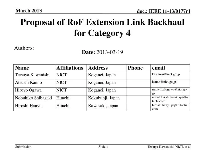
Proposal of RoF Extension Link Backhaul for Category 4. Authors:. Date: 2013-03-19. Abstract.

E N D
Proposal ofRoFExtension Link Backhaul for Category 4 Authors: • Date:2013-03-19 Tetsuya Kawanishi, NICT, et al.
Abstract • RoF (Radio on Fiber) extension link is proposed as one of usage models of 11aj backhaul. RoF extension link can extend wireless access area to the different location without signal degradation and frequency interference. RoF extension link has broadband transmission capability because of O/E and E/O broadband conversion characteristics and can transmit signals at 45-GHz and 60-GHz bands simultaneously. The additional experimental results of RoF extension link are presented. • The aim of this contribution is to add usage model 4c in the IEEE 802.11aj Usage Models Document IEEE 802.11-12/1145r2. Tetsuya Kawanishi, NICT, et al.
Tetsuya Kawanishi, NICT, et al. Overview of WFA VHT usage models for 802.11ad
Tetsuya Kawanishi, NICT, et al. Category 4: Backhaul Multi-Media Mesh Backhaul Hotspot Enterprise Small Office or Home Campus-wide deployments Municipal deployments Point-to-Point Backhaul RoF* Extension Link Backhaul * Radio on Fiber 4
Tetsuya Kawanishi, NICT, et al. Usage Model 4c: RoF Extension Link Backhaul 2nd floor O/E&E/O devices RoF Extension Link O/E&E/O devices Projector 1st floor 1st Access Point
Tetsuya Kawanishi, NICT, et al. Usage Model 4c: RoF Extension Link Backhaul Pre-Conditions: Wirelesszones are connected via RoF extension link. The individual wireless zones can support high-speed-data traffic requirements that are limited by the VHT link capabilities. Application: Traffic is bidirectional and is comprised of subcarriers which include data, voice, video, and any kinds of signals. These subcarriers are equivalent to radio frequencies, i.e. either 45GHz or 60 GHz bands. RoF extension link extends coverage areas without any performance degradation of traffic requirements. Environment: Environment can be home, office, manufacturing floor, etc. Point-to-point link distance can be extended up to 20 km due to low insertion loss of optical fiber cables. Typically locations are Non-Line-of-Sight. No frequency interferences can be managed by use of optical fiber cable. Traffic Conditions: • RoF extension link can carry any type of traffic due to broadband transmission capability of RoF devices. End of each link is heavily loaded with equal amount of traffic in both directions. Use Case: • Wirelessly separated spaces such as rooms of houses surrounded by concretes are directly connected through RoF extension link without any digital signal processing units. • In spite of physical and electromagnetic separation, one wireless zone is extended to another wireless zone which has the same characteristics of the original one. • Users at different locations can take advantage of broadband multi-media applications. 6
2013/1/18 菅野@NICT RoFシステム・実験概略 Tetsuya Kawanishi, NICT, et al. Experimental Setup of RoF Link RoF Tx Optical fiber 0~15 km 100-kHz-linewidth tunable laser Optical band-pass Filter 1 Optical band-pass Filter 2 Mach-Zehnder Optical modulator Er-doped fiber amplifier Photodetector RoF Rx -18 dBm Vector network analyzer Tunable laser: Yenista optics OSICS TLS-AG (Power stability: ±0.03 dB) MZ modulator: GIGOPTIX LX8901 (3-dB BW:>65 GHz) Photodetector: u2t photonics XPDV4120 (3-dB BW:100 GHz) EDFA: Amonics Burst-mode EDFA (Sat. power 20 dBm, NF:<5.5 dB) Bandpass filter1: BW > 1 nm for generation of single sideband signal Bandpass filter2: BW ~ 1 nm for suppression of ASE noises from EDFA
RoFシステムf特測定結果 • Amplitude Deviation:< 2 dBp-p at 40.5-47 GHz • ~ 2 dBp-p at 57-66 GHz Tetsuya Kawanishi, NICT, et al.
RoFシステムファイバ伝送後f特比較 Frequency response of RoF link at 40-48 GHz and 56-67 GHz bands Tetsuya Kawanishi, NICT, et al.
Tetsuya Kawanishi, NICT, et al. Blockdiagram of Single-Side-Band Signal Transmission Experimentof RoF Extension Link using IEEE802.11ad Signal IF OUT. IF IN. 60GHz Tx 60GHz Rx E/O convertor O/E convertor Optical modulator 70-GHz-BW photodiode Laser Optical amplifier Optical BPF Coaxial cable RoF Extension link Optical fiber
Tetsuya Kawanishi, NICT, et al. 60-GHz π/2-BPSK Signal Transmission Experimental Results (1) 180m RoF Extension link RF Back to Back EVM: 3.3%(-29.6dB) EVM: 12.7% %(-17.9dB)
Tetsuya Kawanishi, NICT, et al. 60-GHz π/2-BPSK Signal Transmission Experimental Results (2) Required spectrum mask at channel 4 of 802.11ad Ch.4 (fc=64.80 GHz)
Tetsuya Kawanishi, NICT, et al. 60-GHz 16QAM Signal Transmission Experimental Results Ch.4 (fc=64.80 GHz) EVM:14% (-17dB)
Tetsuya Kawanishi, NICT, et al. EVM (Error Vector Magnitude) vs. Fiber Length EVM (%) Transmission length (m)
Tetsuya Kawanishi, NICT, et al. Delay Time of RoF Extension Link Delay (ns) RoF Back to Back Fiber length (m)
Standards related to Indoor Use of Optical Fiber Cable • IEC60793-2-40 Ed.4.0 Optical fibers – Part 40: Product specifications – Sectional specification for category A4 multimode fibers • Technical Paper published by Optoelectronic Industry and Technology Development Association (Japan) • TP02/BW-2011 - Optical fiber distribution system for apartment houses in FTTH • TP01/BW -2011 - Optical fiber distribution system for detached houses in FTTH • OITDA/TP03/BW-2012 - Optical fiber distribution system for customer premises Tetsuya Kawanishi, NICT, et al.
Summary • RoF extension link backhaul was proposed for Category 4 (Backhaul) • RoF extension link backhaul can extend wireless access area through optical fiber without any change of system requirement. • Data transmission experiment of RoF extension link using 802.11ad signal were presented and EVM of transmitted signals are less 14 %. • Additional delay time is about 350 ns at a fiber cable length of 50 m • Dynamic range of RoF extension link will be discussed at the next meeting. • Acknowledgments: This work was supported in part by “The research anddevelopment project for the expansion of radio spectrum resources" of the Ministry of Internal Affairs and Communications in Japan Tetsuya Kawanishi, NICT, et al.