Download
1 / 48
480 likes | 649 Views
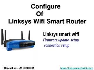
Lab 1 Configuring Wireless Router and PoE Switch. CONVERGENCE TECHNOLOGY CENTER. Equipment used in labs. Linksys Wireless Router. Wireless Router. Used to provide IP addresses to network equipment including IP phones. Linksys Telephony System. Telephony System. Linksys VoIP.

E N D
Equipment used in labs Linksys Wireless Router Wireless Router Used to provide IP addresses to network equipment including IP phones Linksys Telephony System Telephony System Linksys VoIP Linksys Gateway IP-based PBX for a small company Gateway Connects the IP-based phone system to the PSTN Linksys PoE Switch Linksys IP phones and analog phones
DHCP Overview • DHCP (Dynamic Host Configuration Protocol) • Used to send configuration information to end network devices • IP address • Subnet mask • Default gateway • DNS server address • TFTP server (when using Cisco VoIP) • Time server address • Log server address
DHCP Overview (cont.) • For the purpose of the Linksys VoIP labs, the Linksys wireless router is used as a DHCP server and provide Internet connectivity. • When a host attaches to a network and the host is configured for DHCP, the host sends a DHCP request. • The router serving as a DHCP server responds to the request and responds with IP addressing information. • Each time the host powers on, the host could receive a different IP address. • Some devices, such as routers, servers, and printers, need static IP addresses that do not change.
Connect a Host Computer • Connect a laptop or desktop computer to the Linksys wireless router by connecting a straight-through Ethernet cable between the computer NIC and one of the Linksys router ports.
Attach Router Power • Connect the router power brick connector to the wireless router and an AC outlet.
Router Boot Process • Wait a couple minutes for the router to boot. • The router blinks while booting. • Wait for the power light to stop flashing. • Note that this process may take a few minutes to complete.
Router Configuration Router Configuration Reset the router Router Connect a host Access the router Configure DHCP on the router
Reset the Router Press and hold reset button until the power light flashes. Reset
Reboot or Reset PC • Either reboot the PC or release and renew the IP address • The PC should obtain an IP address from the DHCP server (Linksys wireless router)
Access the Router Open a web browser: http://192.168.1.1 Username is admin Password is either blank or admin Access
Configure the Router for DHCP • Setup tab • Basic Setup link • Change the Internet Connection Type to Automatic Configuration-DHCP. • Ensure router IP address is 192.168.1.1 and a subnet mask of 255.255.255.0. • Enable DHCP (select Enabled radio button).
Router DHCP Config. (cont.) 50 addresses – 192.168.1.100 through 192.168.1.149 DHCP • Setup tab (cont.) • Set the DHCP Start IP Address to 192.168.1.100. • Set Maximum Number of Users to 50. • Save the settings (Save Settings button). • Close PC browser.
Switch Configuration Switch Configuration Connect a host and router Switch Update firmware Enable PortFast Enable QoS
Cabling to the Switch Re-cable the router (to port 6) and host (to port 5) to connect to the switch. Re-cable Power Power on the Linksys switch.
Access the Switch On the host open a web browser and access the switch http://192.168.1.254 Username is admin (no password) Access
Latest Firmware • Firmware is software used to control a device. • Update firmware to fix problems or to add/enhance features. • Ensure the firmware is the latest version. • Setup tab • Summary link
Obtain Switch Software Download the firmware from Cisco. Update • Cable the PC to a network that has Internet access. • The file is zipped as shown below. It must be unzipped. • The version number is part of the firmware file name.
Re-cable and Re-access Switch • Reconnect the PC to port 5 on the Linksys switch. • Open a browser and re-access the Linksys GUI environment using the 192.168.1.254 address. • Select the Admin tab • Select the More button
Upgrading Switch Firmware • Select the Firmware Upgrade option. • Select the via HTTP radio button. • Select the Browse button and locate the downloaded and unzipped switch firmware file.
Update the Switch Update Be patient until the update has finished. • Select the Proceed button • Be patient! • Do not use the browser until the software uploads.
Verify Firmware Upgrade • Use the Setup tab and Summary link to verify the firmware upgrade.
Switch IP Addressing • For compatibility in future labs, change the switch IP address to 192.168.1.251 and the default gateway to 192.168.1.254. • Setup tab • Network Settings • Click Save Settings button when finished.
Router IP Addressing • On the PC browser, access the Linksys Wireless router by typing http://192.168.1.1. • Adminis the username with no password
Router IP Addressing (cont.) • Change Internet connection type to Automatic Configuration – DHCP. • Setup tab • Basic Setup link • Configure the IP address to 192.168.1.254. • Ensure the subnet mask is 255.255.255.0 • Save the settings. • Close the browser.
Verify Internet Connectivity • Connect an Ethernet cable between the Linksys wireless router WAN port and a classroom port that connects to the Internet. • On the PC that connects to the Linksys switch, open a browser and connect to a web site such as www.linksys.com. • Do not proceed if Internet access is not available.
PortFast Overview Used on ports that connect to end devices such as phones, printers, PCs, and servers. PortFast • STP (Spanning Tree Protocol) is automatically enabled on a Linksys switch. • Spanning tree is used to block certain redundant ports between switches or bridges so that there is only one path through the Layer 2 network. • PortFast places a switch port in a state that allows packets to be sent immediately through the port.
PortFast Overview (cont.) • Without PortFast, each switch port could take up to 50 seconds before being able to forward traffic. • To avoid timing issues and to allow multicasting to work correctly in the Linksys VoIP system, enable PortFast on ports that will have the SPA9000 and IP phones attached.
Configure Portfast • On the PC connected to the Linksys switch, open a web browser and login to the switch at 192.168.1.251. • Login to the Linksys switch. • From the Spanning Tree tab and STP Port Settings link, change the G1 Port Fast status to Enabled. • Select the Update button.
QoS Overview • QoS (Quality of Service) is enabled on a device to pay attention to marked frames/packets or to mark packets/frames. This marking is used to prioritize network packets. • VoIP can tolerate only 150ms from source to destination. • If voice traffic is delayed or dropped, the conversation sounds garbled, broken, or unacceptable. • QoS should always be implemented when using VoIP.
QoS (Continued) • DSCP (Differentiated Services Code Point) is a six bit value used in the IP header. • This DSCP value can be changed by an end device or a network device through which a packet travels. • The DSCP value can also be “trusted” or “believed” by a network device through which the packet is passing. • VoIP phones automatically mark a voice packet with a very high priority due to the intolerance of delay.
Enable QoS Enable QoS for ports. QoS • On the switch, select the QoS tab and the Basic Mode link.
QoS Configuration • Under the Trust Mode, select DSCP. • Select Save Settings
Time on a Network • Most network devices have the ability to log errors, configuration changes, and events. • These logs have a timestamp—the date and time. • It is important that the date and time are accurate. • Logs from different devices that do not have accurate date and times can make troubleshooting even more challenging.
NTP • NTP (Network Time Protocol) • Servers that provide the accurate date and time. • To configure a device for NTP, you must just configure it with an IP address or name of an NTP server.
NTP Configuration • On the PC, open a web browser. • Access the Linksys switch at 192.168.1.251. • Access the Setup tab and the Time link. • Select the SNTP Time radio button. • Select the appropriate time zone. • Enable the Daylight Savings option and select USA. • Enter a time server IP address. • List at http://tf.nist.gov/tf-cgi/servers.cgi • Select Save Settings. • Configure a second time server.
Switch Admin Tab • Select the Admin tab and the User Authentication link. • In the Local Users Table, select the Admin user name. • Enter the password of Linksys to assign a password to the switch. • Click the Update button. • Click the Save Setting button.
TFTP Server • Used to transfer files quickly, but unsecurely. • Used to upload and download configuration files to a network device. • Download and install the freeware version of a TFTP server from Solarwinds. • Launch the TFTP server. The bottom of the TFTP server screen shows the directory the software expects software to upload or downloaded software will be stored.
TFTP Server Configuration • From the menu, select File and Configure. • Check the status of the server. If stopped, click the Start button.
TFTP Server Configuration • Change the TFTP Server Root Directory to the folder where the Linksys files were downloaded (or will be in the future).
Switch Configuration Backup • Login to the switch. • From the Admin tab, select the Save Configuration link. • Select the via TFTP radio button. • Select the Backup radio button. • Enter the IP address of the PC that has the TFTP server software installed and running. • Change the Destination File name to switch_lab1_startupCfg.cfg
Backup Switch Config (cont.) • Select Proceed button. Click OK. • The PC that has SolarWinds TFTP server software installed shows the process in operation.
Router Backup Configuration • Login to the Linksys wireless router. • Select Administration tab. • Click the Backup Configuration button. • Click the Save button. • Save to the Linksys folder with the file name wireless_router_lab1_WRT300NV1.0_v0.93.9.cfg • Copy all files in the Linksys folder to a USB drive.