Download
1 / 63
630 likes | 747 Views
Development of S-band RF gun and advanced diagnostics in PAL. 박용운 (Yong Woon Park, Ph.D.) 포항 가속기 연구소 (Pohang Accelerator Laboratory, PAL) 포항공과대학교 물리학과 (Physics department) (Pohang University of Science and Technology, POSTECH). Contents. Facilities in PAL

E N D
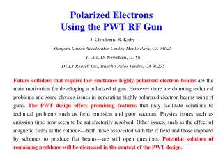
Development of S-band RF gun and advanced diagnostics in PAL 박용운 (Yong Woon Park, Ph.D.) 포항 가속기 연구소 (Pohang Accelerator Laboratory, PAL) 포항공과대학교 물리학과 (Physics department) (Pohang University of Science and Technology, POSTECH) SLAC National Accelerator Laboratory
Contents • Facilities in PAL • S-band RF gun development in PAL • A study of electron beam measurement by using electro-optic crystal • Transverse size measurement of electron beam by using interferometer SLAC National Accelerator Laboratory
Pohang Accelerator Laboratory (PAL), Korea Fs-THz beam line Test facility of injector for XFEL Gun Test facility for XFEL 160-m long 2.5-GeV S-band PLS Linac 2.5-GeV 3rd generation Pohang Light Source (PLS) SLAC National Accelerator Laboratory
Contents • Facilities in PAL • S-band RF gun development in PAL • A study of electron beam measurement by using electro-optic crystal • Transverse size measurement of electron beam by using interferometer SLAC National Accelerator Laboratory
1st - RF gun in PAL, 2005 SLAC National Accelerator Laboratory
Emittance Evolution measurement JJAP. Vol. 46, p.1751 (2007) SLAC National Accelerator Laboratory
1st RF gun in PAL, 2005 SLAC National Accelerator Laboratory
fs-THz Linac Layout Undulator Radiation (future option) OTR FIR • Beam energy : 60 MeV max. • Beam Charge : 0.1 – 0.5 nC • Beam Emittance: < 5 mm-mrad • Beam Pulse Repetition rate: 30 Hz max. • Bunch Length • Before chicane: 0.15 - 2 ps • After chicane: 20 - 200 fs
2nd RF gun in PAL 3rd ILC Asian R&D Seminar, SAMEER, MUMBAI
Cavity and Cathode 3rd ILC Asian R&D Seminar, SAMEER, MUMBAI March 9-10, 2010
Cavity surface – after machining 30 nm RMS~4nm
Cavity surface 40 nm, after cleaning 100 nm RMS~12nm RMS~7nm
Cavity surface 100 nm 40 nm RMS~10nm RMS~10nm
2nd - RF gun in PAL, 2008 Cathode before brazing E-gun after brazing after brazing
RF property of 2nd Gun without tuning pin in wave guide 0-mode π-mode
Experiment in February 2009 Measured energy spread (squares). The electron beam energy is measured as 2.5 MeV. Solid line is Gaussian fit. Axis on the top is the expression of energy spread in terms of the wavelength from 0.0042 Å. The Laser radius at the cathode is 400um. The electron charge is 1pC. The longitudinal shape of laser is Gaussian. The pulse length of laser is 3ps (FWHM). The laser injection phase is 32.5o. SLAC National Accelerator Laboratory
Low energy case with FED condition (a) (b) (a) Measured energy (filled dot) vs injection phase. (b) Measured energy spread (filled dot) vs injection phase. Electron beam energy is measured as 2.5 MeV. Theory (solid line), PARMELA simulation (diamond).
Energy spread effect on FED (b) (a) (a) Diffraction pattern of polycrystalline Al without the energy dispersion (b) Blurred image of the diffraction pattern with 200 keV energy dispersion. Beam energy is 2.5 MeV. where a0 = 4.05 Å is the lattice constant, L is the distance from the sample to the detector, λ is De Broglie wavelength of the electron, and (k, l, m) are Miller indices for the diffraction plane in the aluminum.
High energy cases Measured energy spread . The electron beam energy is measured as 4.8, 5.0, 5.2 MeV. The Laser radius at the cathode is 400um. The electron charge is ~100 pC. The longitudinal shape of laser is Gaussian. The pulse length of laser is 3ps (FWHM). 3rd ILC Asian R&D Seminar, SAMEER, MUMBAI
RF Gun development project2008~2012Budget: 1 M$ (0.2 M$/year) 3rd ILC Asian R&D Seminar, SAMEER, MUMBAI
Basic Concept of Four Ports method Cavity + 4 Ports Cavity + 1 Port Cavity Cavity + 2 Ports By SLAC By POSTECH
Improvement of RF gun Emittance reduction by four ports in full cell Quadrupole mode elimination by adding two side cavities By POSTECH
Test cavity design: four ports RF gun for low power test Test cavity type: BNL/SLAC/UCLA 1.6-cell photocathode RF gun with input waveguide and three symmetric vacuum ports. 3rd ILC Asian R&D Seminar, SAMEER, MUMBAI
Field measurement set up ρ = 10 mm θ x y x z cathode
Low power test result:|Ez| ρ=10 mm x θ Case 1: Cavity + 1 waveguide Case 3: Cavity + 1 waveguide + 3 vacuum ports Case 2: Cavity + 1 waveguide + 1 vacuum port y Coordinates system
3rd RF Gun for fs-THz Facility at PAL Requirements: Vacuum : < 5x10⁻¹⁰ torr Emittance: < 1 mm mrad Operating frequency: 2.856 GHz Field balance(*Eh/**Ef)of π mode: ~1 Mode separation(fπ-f0): ~10 MHz Coupling factor : ~1 Pulse repetition rate: >30 Hz *Eh: Maximum E-field in half cell **Ef: Maximum E-field in full cell In real gun, the tuners will be removed and the ports will be used as vacuum ports.
Cavity and Cathode 3rd ILC Asian R&D Seminar, SAMEER, MUMBAI March 9-10, 2010
Thermal analysis heat generation by the rounded port temperature distribution 59.172 ℃ ~ 107. 406 ℃ temperature distribution 31.408 ℃ ~ 63.149℃ ΔT ~ 48℃ ΔT ~ 21℃ SLAC National Accelerator Laboratory
Brazing of RF Gun and Wave guide brazed at February 2010 Yesterday SLAC National Accelerator Laboratory
Contents • Facilities in PAL • S-band RF gun development in PAL • A study of electron beam measurement by using electro-optic crystal • Transverse size measurement of electron beam by using interferometer SLAC National Accelerator Laboratory
Electro-Optic crystal The refractive indices of the Electro-optic crystal are changed by the electric field from the electron beam. SLAC National Accelerator Laboratory
Coordinates SLAC National Accelerator Laboratory
Principal refractive indices SLAC National Accelerator Laboratory
TEO Timing EO setup in Tunnel 150m Courtesy from A. Azima SLAC National Accelerator Laboratory
SNR enhancement with wave plates SLAC National Accelerator Laboratory
SNR enhancement SLAC National Accelerator Laboratory
Analysis of the electro-optic measurement at FLASH SLAC National Accelerator Laboratory
Experimental setup SLAC National Accelerator Laboratory
Change of laser delay SLAC National Accelerator Laboratory
Quantification of polarization change SLAC National Accelerator Laboratory
Origin of low signal SLAC National Accelerator Laboratory
Contents • Facilities in PAL • S-band RF gun development in PAL • A study of electron beam measurement by using electro-optic crystal • Transverse size measurement of electron beam by using interferometer SLAC National Accelerator Laboratory
Simulated interferogram SLAC National Accelerator Laboratory
1B1 diagnostics beam line in PAL SLAC National Accelerator Laboratory