Download
1 / 17
170 likes | 287 Views
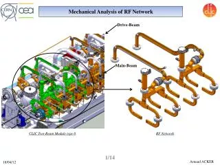
Mechanical Analysis of Dipole with Partial Keystone Cable for the SIS300.

E N D
Mechanical Analysis of Dipole with Partial Keystone Cable for the SIS300 A finite element analysis has been performed to optimize the stresses in the dipole of SIS-300. For this the behavior of the structure during assembly, cool down, magnet operation and the characteristics of the main components are calculated.
Introduction • Distribution of ponderomotive forces in the coil cross-section (there are an azimuth and radial components)
Designs with Yoke Support . Conceptual Design Collared Coil We consider Collared Coil. The stainless steel collars have 3 mm thick (aluminum collar is not considered because of large AC losses). Self-Supported Collared Coils The difference of radial displacements between vertical and horizontal outer radii of the collars of the collars should not exceed 0.05 mm (requirements to field quality) • Differences of displacements between vertical and horizontal outer radii of the collars. Red line is marked permissible differences δR after excitation. Collar wide, mm
The dipole mechanical structure with Yoke Support Yoke has a vertical split, at which magnetic lines go along gap and do not intersect it. A vertically split yoke design has been chosen to provide a reliable support of the collars by the yoke mostly in horizontal direction, where radial forces are the largest. Finite element models 1 - coil, 2 - inter-turn spacers (wedges), 3 - key, 4 –collars, 5 – yoke, 6- cylinder
Magnet mechanics • Collaring An oversized coil is compressed in the press and fixed by keys inserted into collars. Coils force the collar to expand beyond the nominal loose collar dimensions. • Yoking and Cylindering or Assembling Collared coil is compressed by the yoke and cylinder; collar is forced inward. Cylinder halves are welded together. • Cooldown The collared coil shrinks and, it can loss or remains contact with the yoke. Cylinder contracts around the stiffer iron and stress in the cylinder is increased. The yield strength of the cylinder is increased faster than strength in the cylinder. • Excitation Azimuth ponderomotive forces decrease the coil pre-stress at the pole region; however because of there is an opposite large pre-stress, coil remains in contact with the pole. The radial ponderomotive forces act at the collar. These forces are transmitted to the yoke and the cylinder.
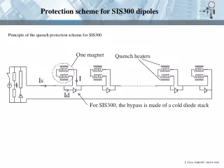
Parameters of contact surfaces contact surface between collar and yoke at angle from 0 to 14 degrees (before key) contact surface between collar and yoke at angle from 14 to 45 degrees contact surface between collar and yoke at angle from 45 to 90 degrees contact surface between yoke and cylinder contact surface between half yokes at the bottom of the iron yoke split contact surface between half yokes at the top of the iron yoke split Yoke-collar, Yoke-Yoke, Yoke-cylinder interfacefor structure with Yoke Support
Design with Yoke Support Open gap structure Close gap structure Variant 1 Variant 2 Gap between half yokes is opened after assembling, closed aftercooling. The collared coil is kept always in contact with the yoke. Gap between half yokes is alwaysclosed. The collared coil loses contact with the yoke after cooling and has contact at 3 T.
Variant 1 Pre-stress change in the superconducting coil layers Collar- yoke interference is 0.05 mm, A vertically split yoke with a tapered gap: gap is 2*0.1 mm at the top and 2*0.07 mm at the bottom, Initial prestress in cylinder is about 80 MPa (interference yoke cylinder is 0.14 mm) • Stages were considered : • Collaring • assembling, • cooling, • excitation (1 T) • excitation (3 T) • excitation (6 T)
Change of radial displacements in pole and median of inner layer during Stages
Pre-stress change in the superconducting coil layers Variant 2 Collar- yoke gap is 0., A vertically split yoke with a tapered gap: gap is 2*0.1 mm at the top and 2*0.07 mm at the bottom, Initial prestress in cylinder is about 80 MPa (interference yoke cylinder is 0.14 mm)
Changes of radialdisplacements in pole and median for inner layer during Stages
Conclusion The study of dipole mechanics showed that it is necessary to have for Close gap structure : yoke - yoke gap: top - 2*0.1mm, bottom - 2*0.07mm Initial prestress in cylinder may be about 80 MPa (interference yoke cylinder is about 0.14 mm) thickness of cylinder is 7 mm Maximal prestress in coil is about 90 MPa. Collar- yoke interference either 0.05 mm or 0. ?