Download
1 / 20
500 likes | 1.47k Views
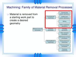
Material Removal Process. Orthogonal cutting Oblique cutting Positive Rake angle Chip away from the workpiece Negative Rake angle Sturdy. Lathe (turning process). Rate of removal = V f w Where V: cutting speed(m/min) f: feed (mm/rev) W: depth of cut (mm). Milling Process.

E N D
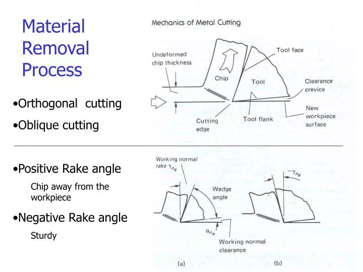
Material Removal Process • Orthogonal cutting • Oblique cutting • Positive Rake angle • Chip away from the workpiece • Negative Rake angle • Sturdy
Lathe (turning process) Rate of removal = V f w Where V: cutting speed(m/min) f: feed (mm/rev) W: depth of cut (mm)
Milling Process Depth of Cut (DOC) Width of Cut (WOC) • Conventional (up) Milling • Recommended, clean surface before machine • Climb (down) Milling • Efficient cut (larger chip) • Less chatter • Production work
Cutting speed (m/min) • V = p D m • Where D = Diameter of cutter (m) • m = Revolution per minute (rpm) • Material Removal Rate (MRR) • MRR = WOC * DOC * f • f = feed rate (mm/min) = n * m * t • Example • V = 50 m/min, t = 0.1 mm/tooth, number of tooth (n)= 2, • D = 4 mm, DOC = 0.2, WOC = 3 • Cutter RPM (m) = 50000/(px4) = 3979 • f = 2 *3979 * 0.1 = 796 mm/min • MRR = 3* 0.2 * 796 = 4776 mm3/min Cutting Tool
Power (1 HP = 0.75 kW) P (kW) = F v Where F: Reaction force (N) v: Cutting speed (m/s) Unit Material Removal Power HPs = HP/MRR
Sources of Errors • Vibration (chatter) • Tool deflection • Temperature change • Run-out • Form Error • Surface Roughness
Chip Formation • Basic Material Behavior-high shear strain • Effected by • Cutting speed (temperature) • Tool angle, friction, vibration
Chip Formation 2 • 1. Discontinuous (segmented) – • brittle materials (ductile materials with high coefficient of friction) • Cast iron, bronze • 2. Continuous • Ideal (tool life & finish) • Ductile materials with low coefficient of friction • 3. Built-up Edge (BUE) • High coefficient of friction – workpiece weld on the tool • Periodical separation of mat -> chatter (vibration) • Can be removed by increasing cutting speed, rake angle, decrease chip thickness
Cutting Forces Merchant model Chip Tool Shear plane angle
Strain Hardening Machined material (chip)has higher hardness than uncut material due to high strain hardening (shear strain, g ~20) Vicker’s indentation test->
Cutting Force For Various Materials Pure Al, Cu are ductile and generate large friction-> low shear plane angle -> large energy consumption
Taylor’s Tool Wear Equation VTn = C logV = logC – nlogT N (HSS) = 0.15 , V = 50m/min N (Tungsten Carbide) = 0.25 , V = 70m/min LogC
Fixture 1-2-3 rule Modular fixture