Download
1 / 42
420 likes | 537 Views
Basic Electronics. Electric Circuit. Components are connected together with electrical wire to form a closed loop. Components are represented by symbols. Electric Circuit. Electrical wire used to connect components is a conductor.

E N D
Electric Circuit Components are connected together with electrical wire to form a closed loop. Components are represented by symbols
Electric Circuit • Electrical wire used to connect components is a conductor. • A conductor allows electric current to flow through it easily. • Good conductors include: copper, gold, silver, tin • Copper wire is generally used as it is most cost effective. • All electrical wires have a plastic cover. • Plastic is an insulator. • An insulator does not allow current to flow through it. • Avoids electric shock. • Insulators include: plastic, glass, wood
Electric Circuit Electric Current is the flow of electrons around a circuit. Electrons have a negative charge
Electric Circuit • Electric current is measured with an Ammeter • The ammeter is placed into the circuit (in series) • Unit of measurement is the Ampere or ‘amp’ • Represented by the letter I
Electric Circuit • EMF (electromotive force) is the force that makes electrons flow around a circuit. • EMF is often called Voltage and is provided by the battery. • Higher voltage = more current
Electric Circuit • Voltage is measured using a Voltmeter. • The voltmeter is placed across a component (in parallel) • Unit of measurement is the Volt. • Represented by letter V.
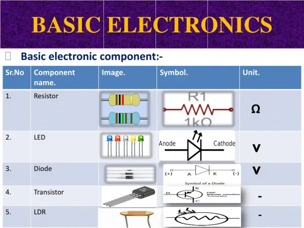
Electric Circuit • Resistance is the opposition to the flow of electric current. • All components have resistance. • Electrical wire has resistance. • Unit of measurement is the Ohm (Ω) • Represented by the letter R
Electric Circuit Resistance is the opposition to the flow of electric current. All components have resistance. Electrical wire has resistance. Unit of measurement is the Ohm (Ω) Represented by the letter R
V I R Ohm’s Law Voltage , Current & Resistance are calculated using Ohm’s Law
Series Circuit • Components are connected one after the other • There is only one path for current to flow around
Series Circuit • The current at all points in a series circuit is equal
Series Circuit • The voltage is shared between the components in a series circuit. • Components of equal resistance – voltage is shared equally
The voltage is shared between the components in a series circuit. • Components of unequal resistance – voltage is shared proportionally Series Circuit
Parallel Circuit • Components are connected side by side • There is more than one path for current to flow around
Parallel Circuit The voltage across each path is always the same as the applied voltage • When component resistance in each path is the same
Parallel Circuit The voltage across each path is always the same as the applied voltage • When component resistance in each path is different
Parallel Circuit The voltage across each path is always the same as the applied voltage • When there is more than one component in a path
Parallel Circuit • The current is divided between the paths proportionally (Ohm’s Law)
Motor Control SPST Switch: Polarity connection determines direction of rotation
Motor Control DPDT Switch: • Forward and reverse control of motor
+V C1 C2 C3 C4 0V Motor Control DPDT Switch
Motor Control DPDT Switch: Wiring Diagram
Motor Control DPDT Switch: Wiring Diagram
Motor Control DPDT Switch: Wiring Diagram
Motor Control DPDT Switch: Wiring Diagram +V 0V
Motor Control Forward and reverse control of motor with limit switches
Motor Control Forward and reverse control of motor with limit switches Wiring Diagram +V 0V
Motor Control Forward and reverse control of motor with limit switches
Motor Control Forward and reverse control of motor with limit switches Wiring Diagram +V 0V
Motor Control Will SW1 and SW2 act as limit switches in this circuit?
Sensors Light Dependent Resistor (LDR) • Resistance increases as darkness increases
Sensors Thermistor • Resistance decreases as the temperature increases
BFY51 BFY51 BFY51 BFY51 Collector Collector Collector Collector Collector Base Base Base Base Base Emitter Emitter Emitter E C B Transistor Acts as a switch Voltage > 0.6V-0.7V between the base and emitter transistor is on
Transistor Voltage Divider circuit is used to create the turn on voltage between the base and emitter.
LDR Transistor Circuit An LDR changes the voltage according to light levels Dark = LED on
Relay A relay is a switch used to turn other circuits on and off Coil terminals are part of controlling circuit DPDT switch
Relay Position A
Relay Position A NC1 NO2 P1
Relay Position B
Relay Position B NO2 NC2 P2