Download
1 / 15
150 likes | 276 Views
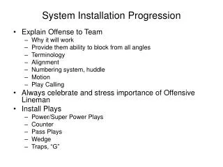
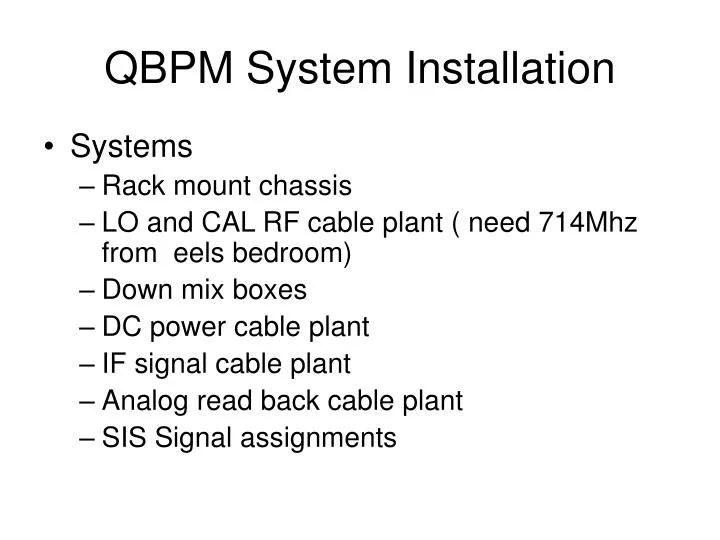
QBPM System Installation. Systems Rack mount chassis LO and CAL RF cable plant ( need 714Mhz from eels bedroom) Down mix boxes DC power cable plant IF signal cable plant Analog read back cable plant SIS Signal assignments. DC power distribution. SLAC supplied. 4 Units.

E N D
QBPM System Installation • Systems • Rack mount chassis • LO and CAL RF cable plant ( need 714Mhz from eels bedroom) • Down mix boxes • DC power cable plant • IF signal cable plant • Analog read back cable plant • SIS Signal assignments
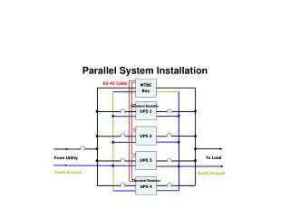
DC power distribution SLAC supplied 4 Units QBPM Rack Layout 40 Rack units required SLAC supplied 1 Unit DC power supply Cable Feed through 2 Units BPM signal patch panel SLAC supplied 4 Units Cable Feed through 2 Units VME crate Could use existing Nanobpm VME crate but should buy a new VME 64x crate Also need a new CPU 9 Units Analog signal interface SLAC supplied 3 Units Cable Feed through 2 Units Need 15V at 5 amps RF amplifier pwr supply 2 Units Cal Tone Generator Still to be designed 4 Units Cable Feed through 2 Units 6446 MHz LO Locking box Existing unit 5 Units
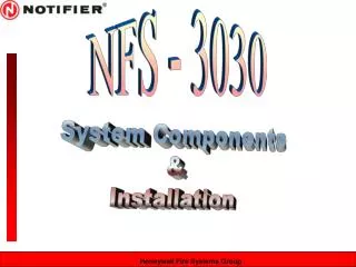
LO power budget/ cable plant 33 dbm max amp output 29.5dbm after splitter 27.6dbm 10m of LDF4-50 cable = 2db plus 0.25 db per connector=2.5db loss 20.13dbm after splitter 26.88dbm 27.6dbm 23.63dbm 26.88dbm 15.63 dbm 24.3dbm 1db loss in these cables 17.6dbm 16.6dbm 16.6dbm All 8 way splitters have 10db loss All cables from 8 way to down mix boxes should have no more than 2db loss These cables should be made from LDF2-50 0.32db/meter 20m of LDF4-50 cable = 4 db plus 0.25 db per connector=4.5db loss 13.5m of LDF4-50 cable = 2.71 db plus 0.25 db per connector=3.25db loss 7m of LDF4-50 cable = 1.4 db plus 0.25 db per connector=1.9db loss
Some where in this location is an ideal location for QBPM electronics 2 way 3 db splitter LDF4-50 cable or equivalent 10db directional couplers 8 way splitters 42 db gain 33dbm amp with 2way splitter LDF2-50 cable
LDF4-50 cable or equivalent 6 way splitter 8 way splitter LDF2-50 cable
Some where in this location is an ideal location for QBPM electronics LDF4-50 cable or equivalent 8 way splitters LDF2-50 cable
Downmix boxes • Downmix boxes and hybrids to be mounted on to the steel plate fixed to the side of the concrete magnet supports • Downmix boxes to be on 25mm standoffs (SLAC supplied) Hybrid Downmix box standoffs
DC Power Distribution Put a connector on the drain wire as shown for grounding the connector shell if needed
DB9 male connector
S I S 1 S I S 5 S I S 2 S I S 4 S I S 3 7 6 5 4 3 2 1 0 7 6 5 4 3 2 1 0 7 6 5 4 3 2 1 0 7 6 5 4 3 2 1 0 7 6 5 4 3 2 1 0 SIS QBPM channel assignments QD16X Y QD16X X QD20X Y QD20X X QM13FF Y QM13FF X QF9AFF Y QF9BFF X QF7FF Y QF7FF X QD12X Y QD12X X QF19X Y QF19X X QM14FF Y QM14FF X QD10AFF Y QD10BFF X QD8FF Y QD8FF X QF11X Y QF11X X QD18X Y QD18X X QM15FF Y QM15FF X QM11FF Y QM11FF X QF9AFF Y QF9AFF X QD10X Y QD10X X QF17X Y QF17X X QM16FF Y QM16FF X QM12FF Y QM12FF X SF6FF Y SF6FF X
S I S 8 S I S 6 S I S S I S 9 S I S 7 7 6 5 4 3 2 1 0 7 6 5 4 3 2 1 0 7 6 5 4 3 2 1 0 7 6 5 4 3 2 1 0 7 6 5 4 3 2 1 0 SIS QBPM channel assignments QF5AFF Y QF5AFF X QF3FF Y QF3FF X QF1FF Y QF1FF X RC3FF RC2FF SF5FF Y SF5FF X QD4AFF Y QD4AFF X SF1FF Y SF1FF X RC1FF RC1X QD0FF Y QD0FF X QF5BFF Y QF5BFF X SD4FF Y SD4FF X QD2AFF Y QD2AFF X SD0FF Y SD0FF X QD6FF Y QD6FF X QD4BFF Y QD4BFF X QD2BFF Y QD2BFF X
Parts to buy to complete RF BPM system • RF BPM LO and CAL cable plant • 500 ft of Andrews LDF4-50 or equivalent LO from source to splitters. With a loss/meter at 6400MHz of 6.5 db/30m. • 44 L4NM-C type N male connectors for both ends. • Flare tool Andrews part# 224363 • Cable preparation tool Andrews part# MCPT-L4 • 1000 ft of Andrews LDF2-50 or equivalent for LO from splitters to electronics. With a loss/meter at 6400MHz of 10.2 db/30m. • 156 L2PNM-HC type N male connectors. • Two 2 way 3db splitters that will work at 33dbm power levels. • Pulsar Microwave PS2-13-450/3N or equivalent • Two 6 way splitters with Type N female connectors. • Pulsar Microwave PS6-06-434/1N or equivalent • Conformal cable and connectors for LO and CAL jumpers. The length of these cables have to be adjusted for the single pulse calibration setup. • 20 meters of 0.140 conformal cable or equivalent. • 80 female N 0.140 connectors • 80 male SMA 0.140 connectors.
Parts to buy to complete RF BPM system (cont) • 21 slot VME crate and controller • Controller type yet to be determined. • 2000m of 6 conductor wire for analog read back. • Wire should be either 18 or 20 gauge with foil shield and drain wire. • 40 male 9 pin D connectors and pins. • D Connector cases should be metal for shielding purposes. • 15 V 5amp rack mount power supply for tunnel LO and CAL amplifiers.
Installation Plan • Install equipment in the rack • Pull in: • LO and CAL cables (still to be purchased) • DC power cables ( now at SLAC) • Analog signal cables (still to be purchased) • IF signal cables ( now at SLAC) • Adjust LO phases for single pulse calibration operation. • Test data acquisition software.