Download
1 / 95
1.01k likes | 1.23k Views
射频工程基础 Fundamentals of RF Engineering. 学时 :60/20 学分 : 3.5. 孙利国 中国科技大学信息学院电子工程与信息科学系. 第六讲 射频应用系统 ( Session 6 RF Application System ). 教材:以课堂讲义为主。 主要参考书: [1] “ Microwave and RF Design: A System Approach”, Michael Steer, SciTech Publishing, 2010 其它参考书:

E N D
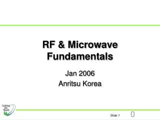
射频工程基础Fundamentals of RF Engineering 学时:60/20 学分: 3.5 孙利国 中国科技大学信息学院电子工程与信息科学系
第六讲 射频应用系统 (Session 6 RF Application System) 教材:以课堂讲义为主。 主要参考书: [1]“Microwave and RF Design: A System Approach”, Michael Steer, SciTech Publishing, 2010 其它参考书: [2] “射频电路设计-理论与应用”,Reinhold Ludwig等著,王子宇等译,电子工业出版社,2002 [3] “射频微电子学”,拉扎维著,余志平等译,清华大学出版社,2006 [4] RF and Microwave Circuit Design for Wireless Communications, Lawrence Larson, Artech House, 1997 [5]”无线网络RF工程:硬件、天线和传播“, Daniel M.Dobkin 著 ,科学出版社 ,2007 [6]”无线通信:原理与应用“ T.S. Rappaport 著, 周文安等译,电子工业出版社,2006. [7]“移动无线通信”, M. Schwartz 著,许希斌等译,电子工业出版社,2006 [8]”Mobile Communications Engineering”, W.C.Y., Lee, McGraw-Hill, 1998
“Microwave and RF Design: A System Approach”, Chapter 3 Radio Frequency System Reading: §3.1 to §3.14 Reference Lecture1 Reading, §3.1 to §3.9
Lecture Outline • Radio Communications • History • Conventional Radio • Cellular Communications • Multiple Access Schemes • Spectrum Efficiency • Cellular Phone Systems
Telegraph Timeline • 1831: Faraday demonstrated the relationship between current and electromagnetism. • 1832; Samuel Morse formed partnership with two colleagues (the ultimate startup) • 1835: Morse, Experimental laboratory telegraph system • 1837: Charles Wheatstone, first commercial telegraph line between London and Camden Town, (2.4 km). • 1844: Morse, commercial two-wire telegraph line from Washington DC to Baltimore. On May 24 of 1844 Morse sent a telegraph message from the Capitol in Washington to Baltimore. This event is recognized as the birth of the communication over the distance using wires. • 1854: 37,000 kilometers of wire crisscrossed the USA . Major users: Railroad; Western Union formed
Telegraph by Morse Morse Code Morse Key It was the combination of Hardware and Coding that made Morse’s system become the dominant telegraph system. Morse taught art at New York University
Wireless Telegraphy + H + + WATER _ _ _ ICE I H1 H2 H2 < H1 Ammeter When particles of ice form in water ice takes on a –ve charge and water a +ve charge. 1865 in West Virginia: Mahlon Loomis is believed the first to achieve non-conducting EM wireless communication but this was not radio. Ice particles are larger and heavier than water drops so ice falls to bottom of cloud. FLOW OF ELECTRONS WHEN SWITCH CLOSED This is induction and not propagation and so range is limited. Loomis was a dentist.
Wireless Telegraphy • 1864: James Maxwell “A Dynamical Theory of the Electromagnetic Field”. Maxwell theoretically showed that light was a wave. He said that Wireless Communication should be possible. • 1875: Edison observed EM sparks and believe this would enable communication without wires. • 1879: Hughes used pulses of sparks to produce radio waves. The Royal Society said that he had it wrong and he was discouraged. • 1885-89: Hertz proved that Maxwell was right. And people believed him. • 1894-1901: Marconi developed first practical radio. The work culminated in the transmission of the telegraph signals across the Atlantic by Marconi in 1901 • 1900-1906: The first radio communication of voice was sent by Fessenden in 1900. In 1906 Fessenden transmitted voice from Massachusetts to Ships in the Atlantic. This milestone is regarded as the beginning of the radio era.
Elements of a Radio Link Information Transmitter Antenna Transmission Line Antenna Receiver Transmission Line Information • Transmitter • Generates RF energy on a desired frequency • Modulates the RF energy to convey information • Antennas • Convert RF energy into electromagnetic fields, vice versa • Focus the energy into desired directions (“gain”) • Receiver • filters out and ignores signals on undesired frequencies • Amplifies the tiny signal sufficiently to allow processing • De-modulates the signal to recover the information
Radio Link Metrics Information Transmitter Antenna Transmission Line Antenna Receiver Transmission Line Information • Transmitter • Power Output • EVM • Antenna System • Gain • Beamwidth • Loss of transmission lines • Receiver • Sensitivity • required minimum signal power level for acceptable performance • Selectivity • degree to which strong signals on nearby frequencies are ignored • Dynamic Range • range of signal strengths between unrecognizably low and threshold of distortion
Basis of Analog Communications Information Source TIME Information Destination Channel Demodulator Modulator AMPLITUDE FDMA Noise FREQUENCY Information Source Information Destination Channel Representation of voice: Voice approx 4 kHz FM modulation Needs 30 kHz bandwidth Each channel has its own dedicated carrier and bandwidth.
Basis of Digital Communications Information Source Encoder Channel Modulator Noise Information Destination Demodulator Decoder TIME AMPLITUDE FDMA/TDMA FREQUENCY
Radio Link Modes AND OR • Simplex • Uses only one channel in “broadcast” mode • Only one talker speaks; listener can’t interrupt • Example: AM, FM broadcasting • Half Duplex • One channel, Bi-directional, but one-way-at-a-time • Only one talker speaks at a time; can’t interrupt • Example: CB, Land Mobile Radio • Duplex • Two channels are used • Both talkers can speak anytime & interrupt • Requires two totally independent channels • Examples: Telephone, Cellular, PCS
Radio Link Modes • FDD and TDD • FDD(Frequency Division Duplex): full duplex • TDD (Time Division Duplex): half-duplex
US Cellular Uplink and Downlink Bands Downlink Uplink Paired Bands Frequency, MHz 824 835 845 849 870 880 890 894 869 891.5 825 846.5 Downlink (“Forward Path”) Uplink (“Reverse Path”) • Cellular telephony provides “full-duplex” communications • two-way simultaneous conversation requires simultaneous voice paths in both directions • 25 MHz. band of frequencies used for uplink (824-849MHz) • 25 MHz. band of frequencies used for downlink (870-894MHz) • Bands separated by 21 MHz (870-849=21MHz) • enables filters to be designed to separate uplink and downlink channels. • Channel bandwidth: 30KHz(one way), 60KHz (duplex channel) • Total channels: 832
What is Cellular Radio? FCC Definition A high capacity land mobile system in which assigned spectrum is divided into discrete channels which are assigned in groups to geographic cells covering a cellular geographic area. The discrete channels are capable of being reused within the service area. The cellular communication • Cellular communication is based on the concept of cells in which a terminal unit communicates with a base station at the center of a cell. • Each cell can be relatively small. • A terminal units travels smoothly from cell to cell with calls transferring using what is called a hand off process.
What is Cellular Radio? The key attributes here are • High capacity • Prior to the availability of the cellular system other radio system were used. Users were not always sure of gaining access to the radio network and frequently had to make three or four attempts to gain access. • The concept of cells • The idea is to divide a large geographic area into cells. • The cells is arranged in clusters. • The total number of channels available (for example 832 in AMPS) is divided among the cells in a cluster. (for example 244 channels /cell if 3 cells/cluster) • Full set is repeated in each cluster. • Cells are often represented as having s hexagonal shape. Actual shape of the cell is influenced by obstructions. • The number of cells in a cluster affects both capacity ( the fewer cells the better) and interference(the more cells per cluster the better) • The size of a cell can be reduced, thus increasing system capacity, in a process called cell splitting.
What is Cellular Radio? The key attributes here are • The concept of cells • The size of a cell can be reduced, thus increasing system capacity, in a process called cell splitting. • In cell splitting, additional base stations are introduced and the base stations and mobile units operate at lower power levels to reduce the geographical coverage or cell size. • Frequency reuse • Frequencies used in one cell are reused in the corresponding cell in another cluster. • As the cells are relatively close, it is important to dynamically control the power radiated by each radio , as radios in one cell will produce interference in other clusters.
Cells Arranged in Different Size Clusters 3 2 1 3 3 2 2 1 7 1 6 2 1 5 3 • For example, in AMPS • Available channels for a cluster: 832 • Total available channels for three clusters: 2496 • The number of cells in a cluster affects both capacity ( the fewer cells the better) and interference(the more cells per cluster the better) • 3 cells/cluster →244 channels /cell • 7 cells/cluster →118 channels /cell • 12 cells/cluster →69 channels /cell 12 4 4 11 7 2 6 10 7 2 12 1 6 2 1 5 4 11 9 3 3 2 5 1 10 5 8 5 3 1 6 4 4 7 9 3 8 12 6 7 11 4 10 2 1 5 9 3 8 6 7 Available channels is divided among cells in a cluster.
Conventional Wireless is Noise Limited 3 3 1 1 2 • Conventional wireless communication • centralized high power transimitter • wide area broadcasting • system transmitters at the same frequency are geographically separated so that the signals fall below the background thresold before same frquencies are reused. • Inteference is solely from background noise. The concept is eliminate cochannel interference from different basestations at same frequency entirely. • There is clearly poor geographical use of spectrum. 2 BACKGROUND NOISETHRESHOLD > 100 km Noise Limited System 10-12 channels per base station Support 1,000 subscribers (poorly).
Cellular Radio is Interference Limited 2 1 2 1 2 7 2 3 7 6 2 6 1 5 3 1 5 4 3 7 1 4 6 7 3 6 7 3 6 5 1 4 3 5 1 5 3 4 7 4 6 7 2 BACKGROUND NOISE 6 2 THRESHOLD 5 5 4 4 10 - 100 km Note region where same frequency signals from both basestations are received. • In a celluar system, • the signals in corresponding cells in different clusters interfere with each other. • generally the interference is much larger than that of the background noise. • Interference can be controlled by dynamically adjusting the base station and mobile transmit powers to the minimum acceptable level. • Operating with interference from neighboring clusters is a key concept in cellular radio. The interference levels that can be tolerated vary among the various cellular systems. for example, minimum SIR is 17dB for AMPS. Interference limited Control co-channel interference and tolerance of co-channel interference built into system Channels divided among all cells in cluster
Milestones in Cellular Radio 1947: Cellular concept was outlined in AT&T Bell Laboratories technical memorandum. 1970: AT&T proposed to build the first high capacity cellular phone system called “Advanced Mobile Phone System(AMPS)” Service (AMPS)”. 1978: First commercial cellular system was launched by Bahrain Telephone Company. This was followed by the launch of AMPS by Illinois Bell and AT&T in the United States in July 1978. 1979: World Administrative Radio Conference (WARC) allocated the 862-960MHz band for mobile radio 1981: FCC released 40MHz in the 800-900MHz band for “cellular land-mobile phone service” 1983: AMPS was first deployed in Chicago by Ameritech.
Milestones in Cellular Radio • Licensed bands at 450 MHz, 900 MHz, 1500, 1700-2300 MHz in different parts of the world. • Cellular Radio • Frequency allocations • AMPS(1G): 850MHz。 • GSM(2G):850、900、1800(DCS)、1900MHz(PCS)。 • CDMA(2G):800MHz、1900MHz • WCDMA(3G): 850、900、1800、1900、2100MHz • LTE(4G):700MHz、2100MHz、2600MHz • Power • Up to 3 W per channel for mobile unit. • Up to 45 W per channel for base station. • Transition from analog to digital radio virtually completes.
Cellular Around the World Cellular Radio is now characterized by “Generations”: First Generation Analog Radio Second Generation Digital Radio Third Generation Wideband CDMA The definition of generations has changed with time. Once Third Generation was (narrowband) CDMA. Now this is referred to as Generation 2.5 • Historically • Cellular Radio (800 - 900 MHz, also 450 MHz) • Personal Communication Services (1700 - 2300 MHz) • Wireless Local Area Networks (150 MHz - 60 GHz) • LMDS (Local Microwave Distribution Service) (28 GHz) • Personal Satellite Communications (5, 28 - 29 GHz) • Low Earth Orbit Satellite (LEOS) Systems (5, 28 GHz)
Multiplexing Modes • Multiplexing • multiplexing (also known as muxing) is a method by which multiple analog message signals or digital data streams are combined into one signal over a shared medium. • Multiplexing technologies may be divided into several types • space-division multiplexing (SDM), • frequency-division multiplexing (FDM), • time-division multiplexing (TDM), • code division multiplexing (CDM). • Similar to highway • Vehicles share highway • Make traffic in order • Divided into lanes (similar to SDM) • Pass one after another (similar to TDM). FREQUENCY
Multiple Access Techniques for Wireless Communications • Multiple access schemes are used to allow mobile users to share simultaneously a finite amount of radio spectrum. • Sharing of spectrum is required to achieve high capacity by simultaneously allocationg the available bandwidth (or available amount of channels) to multiple users. • Multiple access schemes are realized by multiplex techniques. In other words multiplex techniques are extended into multiple access method. Multiplexing is provided by the Physical Layer of the OSI model, while multiple access involves a media access control (MAC) protocol, which is part of the Data Link Layer of the OSI model. • space-division multiplexing (SDM)→space division multiple access(SDMA) • frequency-division multiplexing (FDM)→frequency division multiple access(FDMA) • time-division multiplexing (TDM)→time division multiple access(TDMA) • code division multiplexing (CDM)→code division multiple access(CDMA) FREQUENCY
Multiple Access Techniques for Wireless Communications Frequency Division Multiple Access (FDMA)
Multiple Access Techniques for Wireless Communications Time Division Multiple Access (TDMA)
Multiple Access Techniques for Wireless Communications Code Division Multiple Access (CDMA)
Multiple Access Techniques for Wireless Communications Space Division Multiple Access (SDMA)
Cellular Radio: 1G, 2G, 3G Lecture2 reading, §3.10.3 to §3.14
Cellular Radio: 1G, 2G, 3G • 1G • Analog Modulation • FDMA • Cells and Clusters of Cells • For example AMPS (USA) and ETACS (Europe) • 2G • Digital Modulation • TDMA, CDMA • Cells and Clusters of Cells • For example GSM (Europe, TDMA), CDMAone/2G CDMA (USA, IS-95, CDMA) • 3G • Digital Modulation • Code and Frequency Division Multiple Access(CDMA) • Enormous Processing Gain • Cells but no Clusters • In CDMA system the tolerance to interference is so high that the concept of cluster is not required and every frequency channel is available in each cell. • For example WCDMA (from GSM, CDMA), cdma2000 (from IS-95, CDMA)
Wireless Market Drivers CAPACITY QOS MARKET DRIVERS TECHNOLOGY RESPONSE LTE SERVICES, VIDEO 3G, WCDMA, CDMA2000 HIGH SPEED DATA CDMA CAPACITY/ QUALITY ROAMING GSM (DAMPS) MOBILITY 2000 1980 1990 2010 1970 200 kHz 30 kHz 1.25 MHz 5 MHz BANDWIDTH TIME AMPS
Video Data Requirements Compressed Video Materials MPEG-2 @ ML 640x480i 60 fps 2Mbps –15 Mbps MPEG-2 @ ML 1920x1080i 60 fps 19.3 Mbps Digital Video (full resolution) 25 Mbps Baseband Video MPEG-2@HL 1920x1080 746.496 Mbps FREQUENCY DATA RATE APPLICATIONS 60 GHz work: Low cost, compact circuits: Low phase noise oscillators, Mixer Amplifier, Filter Devices Propagation Analysis Antenna 900 MHz 400 kbps Web browsing, Printer 2.4 GHz 11 Mbps + MPEG-1 wavelet compressed video 5.7 GHz 50 Mbps + MPEG-2 Video 60 GHz 100 Mbps + Baseband Video IR 100 Mbps As above Intensity at this data rate may damage eye UWB IEEE 802.11ne.g. 2–7 GHz 500 Mbps
1G Analog Radio Voltage 00 TIME 10 TIME 30 KHz. Channel AMPLITUDE AMPLITUDE 11 01 FDMA/TDMA fc FDMA FREQUENCY FREQUENCY Quadrature PSK Modulation Also used in 2.5 G Analog modulation: FM modulation or PM modulation. RF Envelope (the amplitude of the RF signal) is constant. 2G TDMA Digital Radio Voltage 30 KHz. Channel fc Frequency Approximately 2 bits per hertz ( a bit less to confine bandwidth)
First Generation (1G) Analog RadioFDMA – Frequency Domain Multiple Access SystemCountries AMPS Advanced Mobile Phone System U.S./Canada Just about retired. RETIRED: TACS Total Access Communication Systems U.K. + 21 countries) NMTS Nordic Mobile Telephone System Nordic countries MATS-E Germany C-450 Germany NTT Japan User 1User 2User 3User 4User 5 TIME AMPLITUDE FREQUENCY FREQUENCY Uses analog modulation: FM modulation or PM modulation. Each channel has its own dedicated carrier and bandwidth. RF Envelope (the amplitude of the RF signal) is constant. All similar in design.
1G Radio AMPS (Advanced Mobile Phone System) • AMPS (Advanced Mobile Phone System): 1G • 800 MHz Cellular FM band • Up-link(TX): 824–849 MHz, 25MHz range • Downlink(RX): 869–894 MHz, 25MHz range • 21 control channels and 395 voice channels (416 channels, FDMA). • Control channels are dedicated to digital data transmissions, providing access and paging functions (FSK). • Voice channels carry the analog voice (FM). • Each AMPS channel has a one way bandwidth of 30 kHz, for a total of 60 kHz for each duplex channel. • Supervisory audio tones (SATs) • SAT is a high pitched, inaudible tone that helps the system distinguish between callers on the same channel but in different cells. One of three tones, at 5970 Hz, 6000 Hz, or 6030 Hz, is transmitted by the base station and repeated back by the mobile. • Blank and Burst • When a base station needs to communicate information to the mobile during a conversation, it will temporarily mute the audio path and send a burst of digital data. These periods, known as blank-and-burst, generally last less than half a second, and are rarely noticed by the user.
1G Radio Analog modulation (as used in first generation) is relatively simple and most of the phone can be realized as discrete parts. Signaling (the process of establishing a call is digital and uses FSK -- Frequency Shift Keying. FM Modulation FM and PM modulation result in a constant RF envelope. The information in the signal is obtained solely in the phase of the RF signal. Separate Voice Channels and Signaling Channels LOWER UPPER CHANNEL ADJACENT ADJACENT OVERLAP OVERLAP CHANNEL CHANNEL AMPLITUDE 0 -30 30 -17.5 -12.5 12.5 17.5
1G Radio LOWER UPPER CHANNEL ADJACENT ADJACENT OVERLAP OVERLAP CHANNEL CHANNEL AMPLITUDE 0 -30 30 -17.5 -12.5 12.5 17.5 Adjacent channels are squeezed to achieve greater spectral efficiency. So there is inherent distortion introduced in the main channel by adjacent channels. This is a necessary compromise because filters with vertical skirts do not exist. Adjacent channels overlap but through frequency planning a basestation does not transmit on adjacent channels. The adjacent channel is used in another cell in the cluster. Transmitted power can be reduced to achieve a minimum acceptable signal-to-interference ratio and by so doing reducing interference in neighboring cells. Also sectoring can be used to minimize interference by redirecting adjacent channels away from each other.
1G Cellular Radio Call FlowFixed-to-Mobile PSTN MSC BASE STATION MOBILE STATION FIXED STATION MOBILE SWITCHING MSC CENTER PUBLIC SWITCHED TELEPHONE NETWORK PSTN BS Basestation MS Mobile Station MSC Mobile switching center PSTN Public switched telephone network In First Generation: (1) Each base station, one at a time, is instructed to send a request to its signaling channel. (2)The base station listens for acknowledgement from mobile terminal. (3) If there is no acknowledgement then the next base station polls. (4) A replying mobile terminal is acknowledged and a voice channel (carrier frequency) is assigned. (5) Exchange of commands and information while the voice channel is active involves blanking the transmit signal and replacing it with an FSK modulated signal.
MSC #1 1G Cellular Radio Call FlowMobile-to-Mobile MSC #1 MSC PSTN MSC MOBILE SWITCHING MSC CENTER BASE STATION PUBLIC SWITCHED MOBILE STATION TELEPHONE NETWORK PSTN (1) Calling mobile issues request on signaling channel. (2) The process is then similar to Fixed-to-Mobile call establishment.
2G (& 3G) Cellular Radio Call FlowFixed-to-Mobile PSTN MSC BASE STATION MOBILE STATION FIXED STATION MOBILE SWITCHING MSC CENTER PUBLIC SWITCHED TELEPHONE NETWORK PSTN (GSM Orientation) BS Basestation MS Mobile Station MSC Mobile switching center PSTN Public switched telephone network In second and third generation, mobile regularly communicates with base station. The system knows where each mobile is. A mobile not in use is still continually monitoring the signaling channel with the strongest signal.
Cellular Call Processing:Mechanics of the Handoff Process Conditions Trigger system to attempt handoff signal strength too low interference or bit error rate too high Measure, Screen alternatives choose surrounding cells to monitor mobile’s strength, report results Analyze Measurements, Select Target Cell Is a better choice available? Is changing worthwhile? Implement Handoff MTX sets up new voice path trunking handoff order sent via blank-and-burst mobile acknowledges and jumps to new voice channel Conversation continues Trigger RSSI Threshold Time B D A C
Cell Assignment and Transmit Power Management To Avoid Interference maintain desired C/I ratio avoid giving, receiving interference in other cells For Operational Reasons for load balancing D C B A Sites B D A C 50 C/I dBm -50 Distance (km)
Second Generation (2G) Digital RadioTDMA – Time Domain Multiple Access Main Systems: DAMPS Digital Advanced Mobile Phone System U.S./Canada (Formerly NADC, North American Digital Cellular, IS-136) GSM Global System for Mobile Communications Europe / World 123456 FDMA/TDMA TIME AMPLITUDE Time FREQUENCY Digital modulation: • In TDMA system, the logical channels are divided in both frequency and time. • Each channel has its own dedicated carrier and time slot.
2G Radio Digital modulation requires a more complex phone. The modulated RF signal has a number of discrete states. Vary amplitude and phase of RF signal Baseband signal has a number of discrete states Divide channels by frequency and time (FDMA/TDMA) Capacity: 3--5 times AMPs Common Digital Modulation Formats: MSK Minimum shift keying. Nonconstant RF envelope. GMSK Minimum shift keying using Gaussian filtered data. Constant RF envelope (can use saturating mode amplifiers). /4 DQPSK on 4 Differential Encoded Quadrature Phase Shift Keying. Not constant RF envelope.
2G Personal Communication Services (In US) In US no standard enforced — left to service provider. Basic (TIA) breakdown. (Telecommunications Industry Association) HIGH TIER Licensed PCS macro-cells, high speed mobility variations of GSM, IS-54/IS-136(DAMPS/NADC/USDC), IS-95(CDMAOne) TDMA/CDMA LOW TIER (Unlicensed PCS, ISM) low speed mobility, low complexity, low power E.G. Bluetooth, 802.11 DECT: Digital European Cordless Telephone CDMA PACS: Personal access communication systems TDMA/FDMA