Download
1 / 34
340 likes | 455 Views
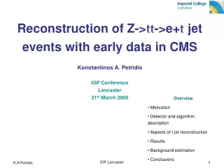
Overview Motivation Description of the electrification numerical scheme Results : (1) single cloud simulations (2) cloud field simulations Summary Conclusions. Motivation Better understanding of differences between lightning activity over land and sea. Focus on the contribution

E N D
Overview • Motivation • Description of the electrification numerical scheme • Results : (1) single cloud simulations • (2) cloud field simulations • Summary • Conclusions
Motivation • Better understanding of differences between lightning activity over land and sea • Focus on the contribution • of geographical factors: • Temperature differences between • land and sea • The coast shape • Topography
The RAMS microphysical scheme • Bulk microphysical scheme • Water categories: vapor, cloud droplets, rain, pristine ice, snow, aggregates, graupel and hail. • A generalized gamma function is assumed for the size spectrum of the categories Processes: nucleation, condensation, evaporation and melting, collision and coalescence, drops breakup, secondary ice production, shedding, sedimentation.
The noninductive charging mechanism T, LWC Graupel Supercooled water Ice particle • Three parameterizations were implemented into the model: • Saunders et al. (1991). • Takahashi (1978, 2002). • Based on Saunders et al. (2003)
The electrification scheme stages • Calculation of the noninductive charging rate of the particles in the cloud. (RAMS) • Interactions of graupel-pristine ice, graupel-snow, graupel-aggregates • Tracking the charge on the particles. (RAMS) • Spatial distribution of charge 3. Calculation of the electric potential from Poisson’s equation. (offline) • 4. Calculation of the electric field from the potential by Gauss’ law. (offline)
Saunders’ scheme Charge per separation event Vg and Vi- terminal fall velocities of the graupel and ice k- constant ( 3 m s-1 ) G(Di) - a polynomial fit to the experimental data of Keith and Saunders (1989)
Takahashi’s scheme Charge per collision Charge (in fC) gained by graupel as a function of temperature and liquid water content. Takahashi (1978)
The polarity of charge gained by graupel 1) Based on the experimental studies of Saunders et al. (1991).(Black bold dashed lines). 2) Based on the experimental results of Takahashi (1978, 2002). (Black thin lines). 3) Based on a modified scheme suggested by Saunders et al. (2003).(Red bold dashed lines).
The noninductive charging rate The rate of change of charge density on graupel particles: Vg and Vi- terminal fall velocities of the graupel and ice DgandDi- diameters Egi– collision-separation-charging efficiency δq– charge per separation event
The electric field Solving for the electric field at all grid points: The electric potential Using a standard numerical solver (NAG) for the electric potential at all grid points by Poisson equation:
Single Cloud Simulation - Setup Bet Dagan – January 5, 2000 Warm-humid bubble initialization Vertical wind shear 1 grid 105 X 105 X 27 cells 32 X 32 X 12 Km
Single Cloud Simulation: Results @ 25 min of simulation
Mass content (g/Kg) at 11 min Cloud drops Pristine ice Snow Graupel
Cloud drops Pristine ice Snow Aggregates Graupel Mass content (g/Kg) at 21 min
Charge density (fC/l) at 11 min with Takahashi’s scheme Pristine ice Snow Graupel Total
Pristine ice Snow Graupel Aggregates Total Charge density (fC/l) at 21 min with Takahashi’s scheme
Total Total Charge density (fC/l) at 21 min with Takahashi’s scheme +1111 +115 -2515
Charge density (fC/l) at 11 min with Saunders’ scheme Pristine ice Snow Graupel Total
Pristine ice Snow Graupel Aggregates Total Charge density (fC/l) at 21 min with Saunders’ scheme
Total Charge density (fC/l) at 21 min with Saunders’ scheme Total +10 -155 +77 +72
Takahashi’s scheme Saunders’ scheme
Total Charge density (fC/l) at 21 min with Saunders’ schemes According to original charging zones According to modified charging zones
19:22 UTC Cloud Field Simulation Clouds over the sea Clouds over the land Cloud water content at 2616 m
Clouds over the sea Charge density (fC/l) with Takahashi’s scheme before first flash. Sea 1 Sea 2 ag ag gr gr Land 1 Land 3 ag ag gr gr Clouds over the land
The maximal electric field in the clouds in the Haifa simulation (Takahashi’s scheme)
Summary • A new electrification scheme was implemented into the mesoscale RAMS model • Simulations of the electrification of a single cloud and a cloud field thunderstorm were performed. • Three parameterizations of the charge separation mechanism were implemented.
Conclusions *Takahashi’s scheme predicts charge distribution (tripole/ dipole) and charging rate that compares well with measurements. * Saunders’ original scheme predicts an inverted dipole (in contrast to observations) until close to first flash. Then, a small upper charge center appears. * Assuming our modification to Saunders’ charging zones, the model predicts a tripole that develops at an earlier stage but with main charge centers in disagreement with observations.
Conclusions * Takahashi’s scheme predicts charge distribution (tripole/ dipole) and charging rate that compares well with measurements. * Saunders’ original scheme predicts an inverted dipole (in contrast to observations) until close to first flash. Then, a small upper charge center appears. * Assuming our modification to Saunders’ charging zones, the model predicts a tripole that develops at an earlier stage but with main charge centers in disagreement with observations.
Conclusions * Takahashi’s scheme predicts charge distribution (tripole/ dipole) and charging rate that compares well with measurements. *Saunders’ original scheme predicts an inverted dipole (in contrast to observations) until close to first flash. Then, a small upper charge center appears. *Assuming our modification to Saunders’ charging zones, the model predicts a tripole that develops at an earlier stage but with main charge centers in disagreement with observations.
Conclusions (cont.) * The stronger dependence of the charging rate on the size of the particles in Saunders’ scheme leads to a lower charging rate than in Takahashi’s. * In clouds that develop over the sea, charging begins later but with a higher rate in comparison to clouds over the land. * The time to the first lightning flash is shorter for clouds that develop over the sea. This could explain the higher frequency of flashes over the Mediterranean Sea.
Conclusions (cont.) * The stronger dependence of the charging rate on the size of the particles in Saunders’ scheme leads to a lower charging rate than in Takahashi’s. * In clouds that develop over the sea, charging begins later but with a higher rate in comparison to clouds over the land. * The time to the first lightning flash is shorter for clouds that develop over the sea. This could explain the higher frequency of flashes over the Mediterranean Sea.
Conclusions (cont.) * The stronger dependence of the charging rate on the size of the particles in Saunders’ scheme leads to a lower charging rate than in Takahashi’s. * In clouds that develop over the sea, charging begins later but with a higher rate in comparison to clouds over the land. *The time to the first lightning flash is shorter for clouds that develop over the sea. This could explain the higher frequency of flashes over the Mediterranean Sea.