Download
1 / 70
710 likes | 857 Views
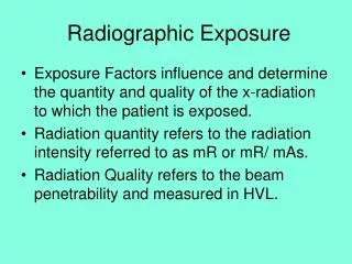
Chapter 18 Radiographic Exposure. Exposure Factors influence and determine the quantity and quality of the x-radiation to which the patient is exposed. Radiation quantity refers to the radiation intensity referred to as mR or mR/ mAs.

E N D
Chapter 18 Radiographic Exposure • Exposure Factors influence and determine the quantity and quality of the x-radiation to which the patient is exposed. • Radiation quantity refers to the radiation intensity referred to as mR or mR/ mAs. • Radiation Quality refers to the beam penetrability and measured in HVL.
Radiographic Exposure • The radiographic exposure factors are under the control of the operator except for those fixed by the design of the x-ray machine. • There are two choices for focal spot. • With the exception of compensating filters, added filtration is fixed. • The type of high voltage power is also fixed.
Exposure Factors Controlled by the Operator • kVp • mA times Exposure Time = mAs • Determines the quality and quantity of the exposure • SID, Focal Spot and Filtration are secondary factors
kVp • As we have discussed in the laboratory, kVp controls radiographic contrast. • kVp determines the ability for the beam to penetrate the tissue. • kVp has more effect than any other factor on image receptor exposure because it affects beam quality.
kVp • To a lesser extent it also influences the beam quantity. • As we increase kVp, more of the beam penetrates the tissue with higher energy so they interact more by the Compton effect. • This produces more scatter radiation which increases image noise and reduces contrast.
kVp • 50 kV 79% is photoelectric, 21% Compton, < 1% no interaction • 80 kVp 46% is photoelectric, 52% Compton 2% no interaction • 110 kVp 23% photoelectric, 70% Compton, 7% no interaction • As no interaction increases, less exposure is needed to produce the image so patient exposure is decreased.
mA • 1 Ampere = 1 C/s = 6.3 x 10¹⁸ electrons/ second. • The mA selected for the exposure determines the number of x-rays produced. • The number of x-rays are directly proportional to the mA assuming a fixed exposure time. • 100 mA produced half the x-ray that 200 mA would produce.
mA • Patient dose is also directly proportional to the mA with a fixed exposure time. • A change in mA does not affect kinetic energy of the electrons therefore only the quantity is changed.
mA • Many x-ray machines are identified by the maximum mA or mAs available. • A MP 500 has a maximum mAs of 500 mAs. • A Universal 325 has a maximum mA of 300 and maximum kVp of 125
mA • More expensive three phase machines will have a higher maximum mA. • A General Electric MST 1050 would have 1000 mA and 150 kVp.
Exposure Time • The exposure time is generally always kept as short as possible. • This is not to reduce patient exposure but to minimize motion blur resulting from patient movement. • This is a much greater problem with weight bearing radiography.
Exposure Time • Older machine express time as a fraction. • Newer machines express exposure time as milliseconds (ms) • It is easy to identify the type of high voltage generation by looking at the shortest exposure time.
Exposure Time • Single phase half wave rectified fasted exposure time is 1/60 second 17 ms. • Single phase full wave rectified fastest exposure time is 1/120 second or 8 ms • Three phase and high frequency can provide exposure time down to 1 ms.
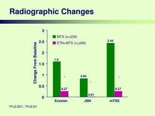
mAs • mA and exposure time is usually combined and used as one factor expressed as mAs. • mAs controls radiation quantity, optical density and patient dose. • mAs determine the number of x-rays in the beam and therefore radiation quantity. • mAs does not influence radiation quality.
mAs • Any combination of mA and time that will give the same mAs should provide the same optical density on the film. This is referred to as the reciprocity law. • As noted earlier for screen film radiography, 1 ms exposure and exposure longer than 1 seconds do not follow this rule.
mAs • On many modern machines, only mAs can be selected. The machine automatically gives the operator the highest mA and shortest exposure time. • The operator may be able to select mA by what is referred to as Power level.
mAs • mAs is one way to measure electrostatic charge. It determines the total number of electrons. • Only the quantity of the photons are affected by changes in the mAs. • Patient dose is therefore a function of mAs.
mAs • If we know the mR/mAs, multiply that figure times the mAs. or • If we know the mR for a given exposure at a given kVp, we can divide the exposure by the mAs to get the mR/ mAs. • To compute exposure we need to know what the mR/mAs is for the kVp used and the SID.
Distance • Distance affects the exposure of the image receptor according to the inverse square law. • Distance affects the intensity of the x-ray beam at the film but has no effect on radiation quality.
Inverse Square Law • mAs (second exposure) SID2 2nd exposure • ----------------------------= ------------------------- • mAs (first exposure) SID2 1st exposure
Distance • The most common source to image distances are 40” (100 cm) and 72”(182 cm) • Since SID does not impact the quality of the beam, adjustments to the technical factors are made with the mAs. • To go from 40” to 72” increase the mAs 3.5 time.
Distance • Increasing the distance will impact the geometric properties of the beam. • Increased SID reduces magnification distortion and focal spot blur. • With the need to increase the mAs 3.5 times for the 72” SID, tube loading becomes a concern.
Distance • 72” SID is used for Chest radiography and the lateral cervical spine to reduce magnification. • 72” SID used for the full spine to get a 36” beam.
Imaging System Characteristics • Operator has limited control. • The following will impact the technical factors based upon the type of machine. • Focal Spot Size • Filtration • High-voltage Generation
Focal Spot Size • Most machines limited to two focal spot sizes. • Common office focal spots are 1.0 mm for the small and 2.0 mm for large. • Highly detailed radiography such as mammography use micro-focus tubes with 0.1 mm and 0.3 mm focal spot sizes.
Focal Spot Size • The focal spot size limits the tube’s capacity to produce x-rays. The electrons and resulting heat are placed on a smaller portion of the x-ray tube. • The mA is therefore limited for the small focal spot. This results in longer exposure times with greater chance of patient movement.
Focal Spot Size • For single phase machines, the small focal spot use is limited to extremities and the cervical spine. • With high frequency, most views can be done on the small focal spot except for larger patient and ones that cannot hold still. • My limit is exposure times less than 1/2 s.
Focal Spot Size • If the mA is properly calibrated, the focal spot will have no impact on the quantity or quality of the beam.
Filtration • All x-ray beams are affected by the filtration of the tube. The tube housing provides about 0.5 mm of filtration. • Additional filtration is added in the collimator to meet the 2.5 mm of aluminum minimum filtration required by law. • 2.5 mm is required for 70 kVp.
Filtration • 3.0 mm is required for at 100 kVp. • 3.2 mm is required for operations at 120 kVp. • Most machines now are capable of over 100 kVp operation. • We have no control on these filters.
Filtration • Chiropractic radiography is a leader in the use of compensating filters. We have total control over compensating filtration. • In areas of the body with high subject contrast or wide differences in density, compensating films improve image quality and reduce patient exposure.
High-voltage Generation • You will determine the type of high-voltage generation when you purchase your x-ray machine. • The type of generator will determine the efficiency of the generator or the amount of ripple in the wave form. • Single phase has 100% ripple.
Three Phase Generation • Three phase has a 14% so it is significant improvement in efficiency increasing both quality and quantity of the beam. • More x-rays per mAs with higher energy. • Cost to provide 3 phase power is very high so not practical in office.
High Frequency Generation • Virtually no ripple ( less than 1%.) • Inexpensive and can use normal incoming power. • Provides significant reduction is mAs or kVp compared to single phase. Reduction of mAs by 50% compared to single phase techniques.
Chapter 19 Radiographic Quality • Radiographic Quality refers to the fidelity with which the anatomic structures being examined are images on the film. • Three main factors: • Film Factors • Geometric Factors • Subject Factors
Radiographic Quality • Characteristic of radiographic quality: • Spatial Resolution (Recorded Detail) • Contrast Resolution (Visibility of Detail) • Noise (Visibility of Detail) • Artifacts
Spatial Resolution • Spatial Resolution is the ability to image small structures that have high subject contrast such as bone-soft tissue interface. • When all of the factors are correct, conventional radiography has excellent spatial resolution.
Contrast Resolution • Contrast resolution is the ability to distinguish structures with similar subject contrast such as liver-spleen, fat-muscle. • Computed tomography and MRI have excellent contrast resolution. Convention radiology is fair to poor.
Noise • Noise is an undesirable fluctuation in optical density of the image. Two major types: • Film Graininess- no control over • Quantum Mottle- some control over
Film Graininess • Film graininess refers to the distribution in size and space of the silver halide grains in the film emulsion. • Similar to photographic film. 400 ASA film is more graininess than 100 ASA film. • Similar to structure mottle that refers to the size and shape of the phosphors in the intensifying screens.
Quantum Mottle • Quantum mottle refers to the random nature of how the x-rays interact with the image receptor. • It is the primary form of radiographic noise. • The use of high mAs and low kVp reduced quantum mottle.
Quantum Mottle • Very fast screens have higher quantum mottle because it takes fewer x-rays to make the image.
Speed • Resolution and noise are intimately connected with speed. • While the speed of the images receptor is not apparent on the image, it influences both resolution and noise.
Radiographic Quality Rules • Fast Image receptors have high noise and low spatial and contrast resolution. • High spatial and contrast resolution require low noise and slow image receptors. • Low noise accompanies slow image receptors with high spatial and contrast resolution.
Film Factors of Quality • Characteristic curve • Density • Contrast • Latitude • Processing • Time • Temperature
Sensitometry • Sensitometry is the study of the relationship between the intensity of exposure of the film and the blackness after the film is processed. • Unexposed film is clear with a blue tint after processing. • Exposed film is black after processing.
Sensitometry • Two principles involved. • Exposure of the film • Amount of light transmitted through the processed film of optical density. • Used to describe the relationship of radiation exposure and blackness or density on the film.
Characteristic Curve • This relationship is called the characteristic curve or H & D curve of the film. • H & D stands for Hurter and Driffield.
Parts of the Characteristic Curve • Toe and shoulder where large changes in exposure results in small changes in OD. • Very high and very low variations of exposure make very small changes in density.
Parts of the Characteristic Curve • The straight line or intermediate area is where very small changes in exposure results in large changes in density. • This is the important part of the curve in radiography.